18.3.3 High Speed Pulse Output Mode
When the count value of the PCA counter matches the value of the capture register, the CCPn output of the PCA
module will hop. To activate the high speed pulse output mode, the TOGn, MATn, and ECOMn bits of the CCAPMn
register must be set.
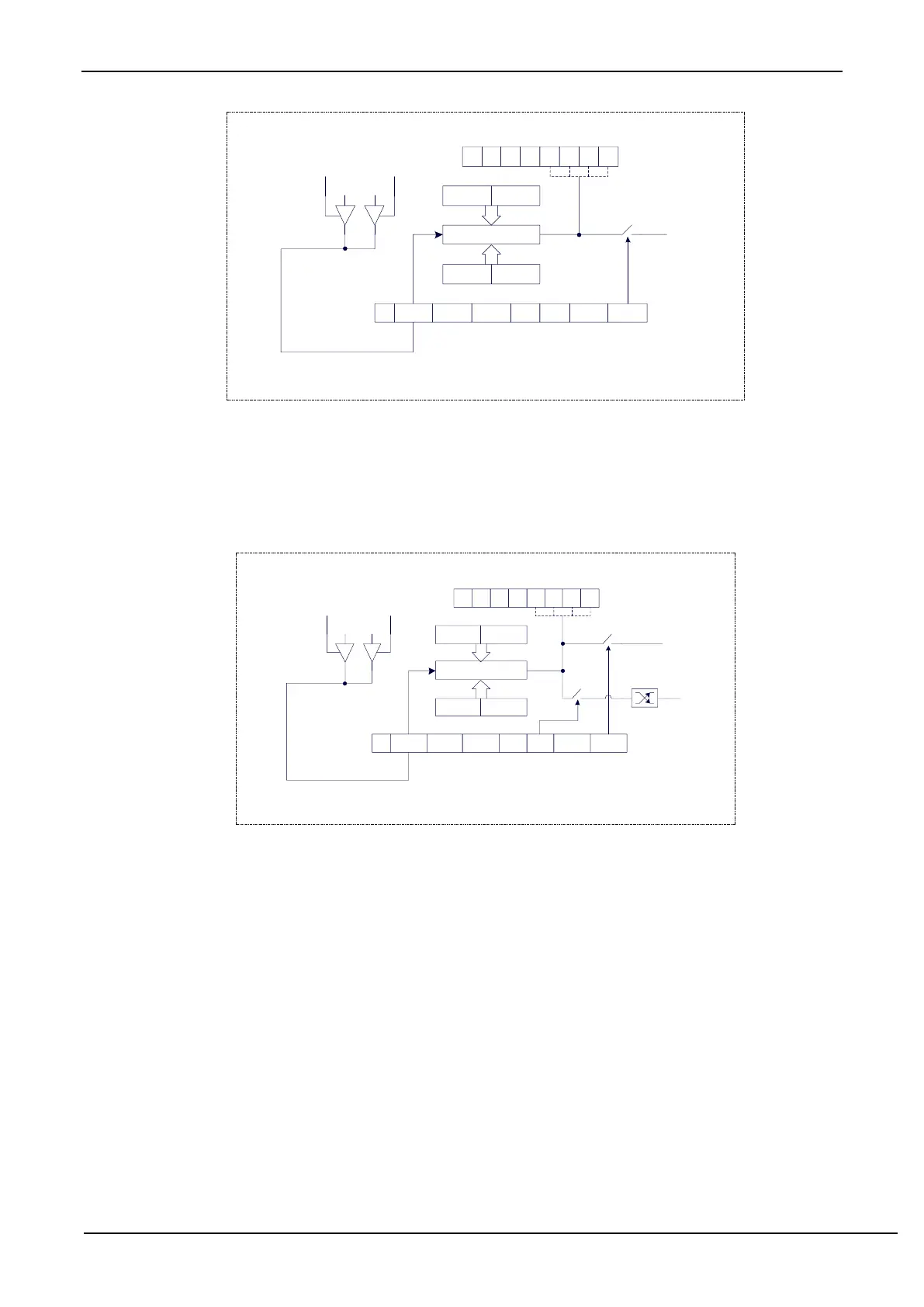
The structure of PCA module working in high-speed pulse output mode is shown below.
PCA high speed pulse output mode
0 1 1 0
CCAPMn
- ECOMn CAPPn CAPNn MATn TOGn PWMn ECCFn
CF CR - - CF3CF2CF1CF0
CCON
CH CL
CCAPnH CCAPnL
0 0
16 bit comparator
0 1
CCPn
ECOMn=0, stop comparison
ECOMn=1, continue comparison
Write
CCAPnL
firstly
Then
write
CCAPnH
enable matched
PCA
interrupt
18.3.4 Pulse Width Modulation Mode (PWM mode)
18.3.4.1 8-bit PWM Mode
Pulse width modulation is a technique that uses a program to control the duty ratio, cycle and phase of a waveform.
It is widely used in applications such as three-phase motor driving and D/A conversion. The PCA modules of the STC8G
series of microcontrollers can be configured to operate in 8-bit, 7-bit, 6-bit or 10-bit PWM mode by setting
corresponding PCA_PWMn registers. To enable the PWM function of the PCA module, the PWMn and ECOMn bits
of the module register CCAPMn must be set.
When EBSn [1:0] in the PCA_PWMn register is set to 00, PCAn operates in 8-bit PWM mode, where {0, CL [7:
0]} is compared with the capture registers {EPCnL, CCAPnL [7: 0]}. When PCA modules are operating in 8-bit PWM
mode, the output frequencies of them are the same because all the modules share a single PCA counter. The output duty
ratio of each module is set using the registers {EPCnL, CCAPnL [7: 0]}. The output is low when the value of {0, CL
[7: 0]} is less than {EPCnL, CCAPnL [7: 0]}, and the output is high when the value of {0, CL [7: 0]} is equal to or
greater than {EPCnL , CCAPnL [7: 0]}. When CL [7: 0] overflows from FF to 00, the contents of {EPCnH, CCAPnH