STC8A8K64D4 Series Manual
14.6 UART4
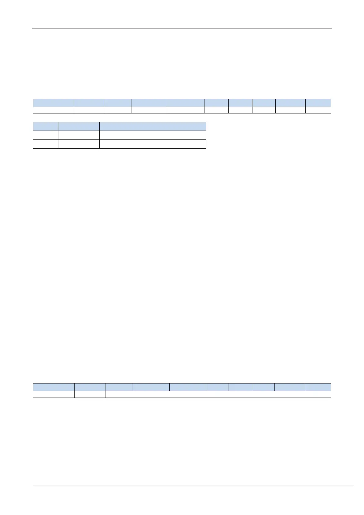
14.6.1 UART4 control register
S4SM0: UART4 mode select bit.
8-bit UART, whose baud-rate is variable
9-bit UART, whose baud-rate is variable
S4ST4: UART4 baud rate generator select bit.
0: Select T2 as the baud-rate generator of UART4.
1: Select T4 as the baud-rate generator of UART4.
S4SM2: UART4 multi-machine communication control bit. In mode 1, if the S4SM2 bit is 1 and the S4REN bit is 1,
the receiver is in the address frame filter state. In this case, the received 9
th
bit (S4RB8) can be used to filter the
address frame. If S4RB8 = 1, the frame is the address frame, address information can enter S4BUF, S4RI
becomes 1, and then address can be compared with the slave address in the interrupt service routine. If S4RB8
= 0, it indicates that the frame is not an address frame and should be discarded and keep S4RI = 0. In mode 1,
if the S4SM2 bit is 0 and the S4REN bit is 1, the receiver is in the address frame filter disabled state. Regardless
of the received S4RB8 is 0 or 1, the information received can enter into the S4BUF, and make S4RI = 1. Here,
S4RB8 is usually used as parity check bit. Mode 0 is non-multi-machine communication mode, where S4SM2
should be 0.
S4REN: Receive enable control bit.
0: disable UART4 receive data.
1: enable UART4 receive data.
S4TB8: S4TB8 is the 9
th
bit of datum to be sent when UART4 is in mode 1, which is usually used as a parity check bit
or an address frame / data frame flag. It can be set or cleared by software as required. In mode 0, this bit is not
used.
S4RB8: S4RB8 is the 9
th
bit of datum recieved when UART4 is in mode 1, which is usually used as a parity check bit
or an address frame / data frame flag. It can be set or cleared by software as required. In mode 0, this bit is not
used.
S4TI: Transmit interrupt request flag of UART4. S4TI is set by the hardware automatically at the beginning of the stop
bit transmittion and requests interrupt to the CPU. S4TI must be cleared by software after the interrupt is
responded.
S4RI: Receive interrupt request flag of UART4. S4RI is set by hardware automatically at the middle of stop bit the
serial port received, and requests interrupt to the CPU. After the interrupt is responded, S4RI must be cleared
by software.
14.6.2 UART4 data register
S4BUF: It is used as the buffer in transmission and receiving for UART4. S4BUF is actually two buffers, reading buffer
and writing buffer. Two operations correspond to two different registers, one is write-only register (writing
buffer), the other is read-only register (reading buffer). The CPU reads serial receive buffer when reads S4BUF,
and writes to the S4BUF will trigger the serial port to start sending data.
14.6.3 UART4 Mode 0
UART4 mode 0 is an 8-bit UART mode with variable baud rate, where a frame of data consists 10 bits: 1 start bit,
8 data bits (LSB first) and 1 stop bit. The baud rate is variable, which can be set by the software as needed. TxD4 is the