20.3.2 Dual Devices Configuration Mode
Two devices are connected, the master and the slave are not fixed.
Setting Method 1: Both devices are initialized with SSIG set to 0, MSTR set to 1, and SS pin set to bi-directional
mode and output high. Now the both devices are in master mode with not ignoring SS. When one of the devices needs
to initiate a transfer, set its own SS pin to output mode and output low to pull down the other device's SS pin so that the
other device is forcibly set to slave mode.
Set Method 2: Both devices are initialized as slave mode with ignoring SS, where SIG is set to 1 and MSTR is set
to 0. When one of the devices needs to initiate a transfer, detect the SS pin's level firstly. If SS is high, the device sets
itself to master mode with ignoring SS, then starts the data transfer.
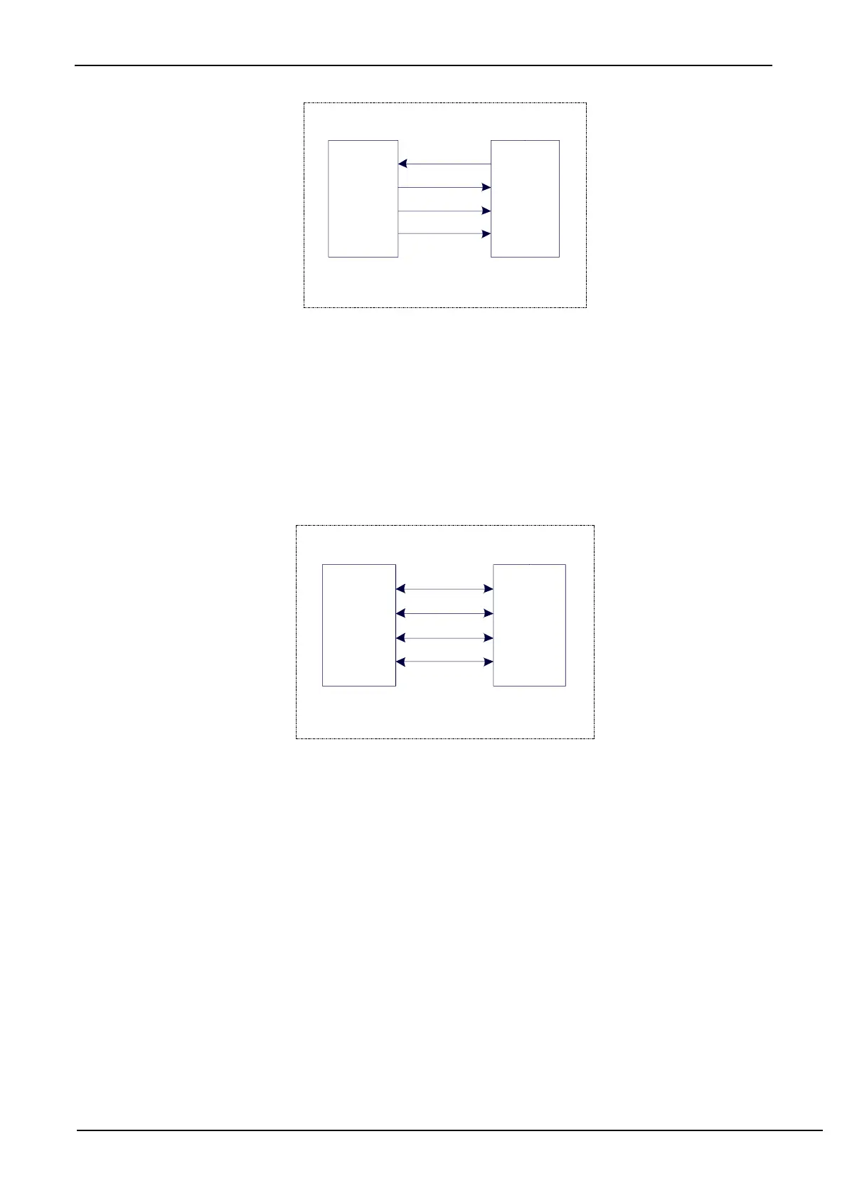
The connection configuration of dual devices configuration mode is shown as follows:
20.3.3 Single Master and Multiple Slaves Mode
Multiple devices are connected, one of which is fixed as a master and others are fixed as slaves.
Master settings: SSIG set to 1, MSTR set to 1, fixed to master mode. The master can use any port to connect with
the SS pins of each slave respectively, and pull down the SS pin of one slave to enable the corresponding slave device.
Slave settings: SSIG is set to 0, SS pin is used as the chip select signal of the slave.
The configuration diagram of single master multiple slaves is as follows: