will be written to RL_TL0 at the same time, and the content written to TH0 will also be written to RL_TH0 at the same
time. When TR0=1, that is, when Timer/Counter0 is allowed to work, writing content to TL0 is not actually written to
the current register TL0, but written to the hidden register RL_TL0, and writing content to TH0 is actually also it is not
written into the current register TH0, but into the hidden register RL_TH0, which can cleverly realize the 16-bit reload
timer. When reading the contents of TH0 and TL0, the contents be read are the contents of TH0 and TL0, not the
contents of RL_TH0 and RL_TL0.
When Timer0 is working in mode 0 (TMOD[1:0]/[M1,M0]=00B), the overflow of [TH0,TL0] not only sets TF0,
but also automatically reloads the contents of [RL_TH0,RL_TL0] to [TH0,TL0].
If T0CLKO/INT_CLKO.0=1, the P3.5/T1 pin is configured as timer 0's clock output T0CLKO. The output clock
frequency is T0 overflow rate/2.
If C/T=0, the timer/counter 0 counts the internal system clock, then:
if T0 works in 1T mode (AUXR.7/T0x12=1), the output clock frequency = (SYSclk)/(65536-[RL_TH0,
RL_TL0])/2
if T0 works in 12T mode (AUXR.7/T0x12=0), the output clock frequency = (SYSclk)/12/(65536-[RL_TH0,
RL_TL0])/2
If C/T=1, the timer/counter 0 counts the external pulse input (P3.4/T0), then:
the output clock frequency = (T0_Pin_CLK) / (65536-[RL_TH0, RL_TL0])/2
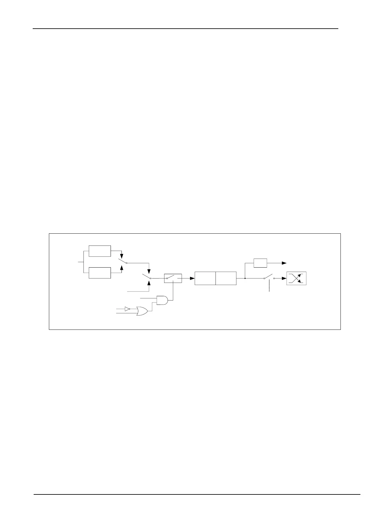
13.2.4 Timer0 mode 1 (16-bit non-autoreloadable mode)
In this mode, Timer/Counter 0 works in 16-bit non-reloadable mode, as shown in the figure below.
Timer/counter 0 mode 1: 16-bit non-reloadable mode
In this mode, Timer/Counter 0 is configured as a 16-bit non-reloadable mode, which is composed of 8 bits of TL0
and 8 bits of TH0. The 8-bit overflow of TL0 carries over to TH0, and the overflow of TH0 counts the overflow flag
TF0 in TCON.
When GATE=0 (TMOD.3), the timer will count if TR0=1. When GATE=1, it is allowed to control timer 0 by
external input INT0, so that pulse width measurement can be realized. TR0 is the control bit in the TCON register. For
the specific function description of each bit of the TCON register, see the introduction of the TCON register in the
previous section.
When C/T=0, the multiplexer is connected to the frequency division output of the system clock, T0 counts the
internal system clock, and works in timing mode. When C/T=1, the multiplexer is connected to the external pulse input
P3.4/T0, and T0 works in counting mode.
Timer0 of STC microcontroller has two counting rates: one is 12T mode, which is increased by 1 for every 12
clocks, which is the same as traditional 8051 microcontroller, the other is 1T mode, which is increased by 1 for each
clock, and the speed is 12 times of traditional 8051. The rate of T0 is determined by T0x12 in the special function
register AUXR. If T0x12=0, T0 works in 12T mode, and if T0x12=1, T0 works in 1T mode.