16-bit auto-reload mode.
When the 16-bit counter [TH0, TL0] overflows, the system loads the reload value in
the internal 16-bit reload register into [TH0, TL0] automatically.
16-bit auto-reload mode. It is similar to mode 0, whose interrupt can not be disabled.
The interrupt has the highest priority, higher than the priority of all other interrupts,
and cannot be turned off. It can be used as the system tick timer of the operating
system or the system monitoring timer. The only way to stop is to turn off the TR0
bit in the TCON register and stop supplying the clock to Timer 0.
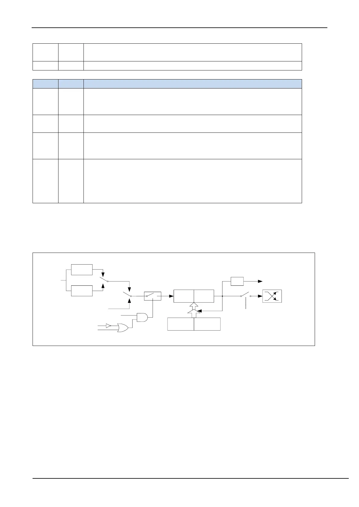
Timer/Counter0 mode 0: 16-bit auto-reload mode
When GATE=0 (TMOD.3), the timer will count if TR0=1. When GATE=1, it is allowed to control timer0 by
external input INT0, so that pulse width measurement can be realized. TR0 is the control bit in the TCON register. For
the specific function description of each bit of the TCON register, see the introduction of the TCON register in the
previous section.
When C/T=0, the multiplexer is connected to the frequency division output of the system clock. T0 counts the
internal system clock, and works in timing mode. When C/T=1, the multiplexer is connected to the external pulse input
P3.4/T0, and T0 works in counting mode.
Timer0 of STC microcontroller has two counting rates: one is 12T mode, which is increased by 1 for every 12
clocks, which is the same as traditional 8051 microcontroller, the other is 1T mode, which is increased by 1 for each
clock, and the speed is 12 times of traditional 8051. The rate of T0 is determined by T0x12 in the special function
register AUXR. If T0x12=0, T0 works in 12T mode, and if T0x12=1, T0 works in 1T mode.
Timer0 has two hidden registers RL_TH0 and RL_TL0. RL_TH0 and TH0 share the same address, and RL_TL0
and TL0 share the same address. When TR0=0, that is, when Timer/Counter0 is disabled, the content written to TL0