STC8A8K64D4 Series Manual
15 Comparator, Power-down Detection, Internal
Reference Voltage
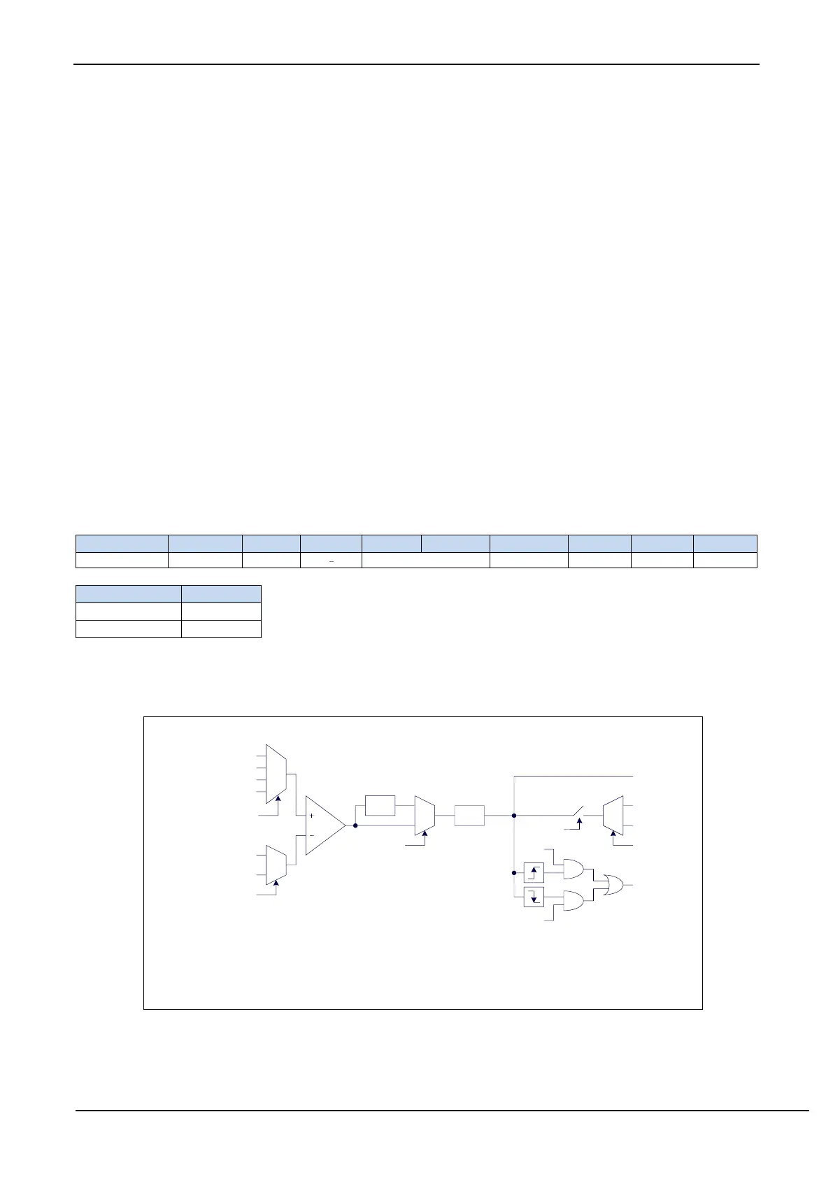
A comparator is integrated in STC8A8K64D4 series of microcontrollers. The positive terminal of the comparator
can be P3.7, P5.0, P5.1 or ADC analog input, and the negative can be P3.6 or the REFV voltage of the internal BandGap
after amplified. The application of multiple comparators can be realized through multiplexer and time division
multiplexing.
There are two stage programmable filterings inside the comparator: analog filtering and digital filtering. Analog
filtering can filter out glitches in the input signal, and digital filtering can wait for the input signal to stabilize before
making a comparison. The result of the comparison can be obtained directly by reading the internal register bits or
output the result of the comparator forward or reverse to the external port. Outputting the comparison result to the
external port can be used as the trigger signal of external events and the feedback signal to expand the scope of
application.
15.1 Comparator output pin switching
CMPO_S: Comparator output pin select bit
15.2 Internal Structure of Comparator
0.1us
0
1
0
1
LCC
0
1
PIE
NIE
CMPO_S
P4.1
P3.4
CMPIF
CMPOE
CMPRES
DISFLT
CMPPS
CMPNS
P3.7
P3.6
Internal REFV(1.19V)
ADCIN
analog filtering
digital filtering
The internal structure of
Comparator
Delay LCDTY
CPU clocks
0
1
2
3
P5.0
P5.1
ADCIN include ADC0, ADC1, ADC2, ADC3, ADC4, ADC5, ADC6, ADC7,
ADC8, ADC9, ADC10, ADC11, ADC12, ADC13, ADC14, ADC15
Note: When the ADC input channel is s e l e c t e d a s the positive pole of the
comparator, be sure to turn on the ADC power control bit ADC_POWER and the
ADC channel selection bit ADC_CHS in the ADC_CONTR register.