STC8A8K64D4 Series Manual
14.7 Precautions of UARTs
Regarding the UART interrupts requests, the following issues need to be noted. UART1, UART2, UART3, and
UART4 are all similar, and serial port 1 is used as an example below.
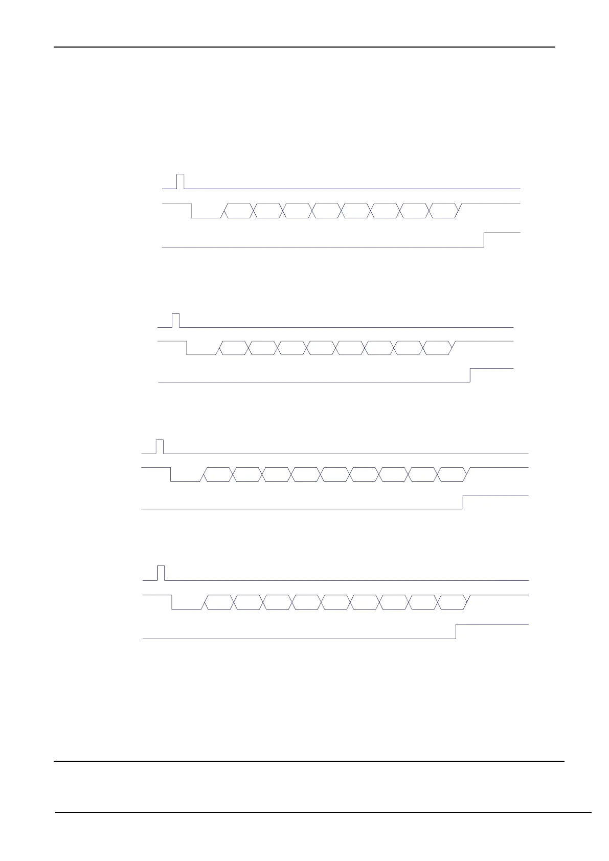
In 8-bit data mode, TI interrupt request is generated after the entire stop bit is transmitted, as shown in the following
figure:
Write
SBUF
TxD
TI
D0 D1 D2 D3 D4 D5 D6 D7Start Stop
Transmission data (8-bit data)
In 8-bit data mode, RI interrupt request is generated after half of the stop bit is received, as shown in the following
figure:
Write
SCON
RxD
RI
D0 D1 D2 D3 D4 D5 D6 D7Start Stop
REN=1, RI=0
Receiving data (8-bit data)
In 9-bit data mode, TI interrupt request is generated after the entire 9
th
data bit is transmitted, as shown in the
following figure:
Write
SBUF
TxD
TI
D0 D1 D2 D3 D4 D5 D6 D7Start Stop
Transmission data (9-bit data)
TB8
In 9-bit data mode, RI interrupt request is generated after receiving half of the 9
th
bit, as shown in the following
figure:
Write
SCON
RxD
RI
D0 D1 D2 D3 D4 D5 D6 D7Start Stop
Receiving data (9-bit data)
RB8
REN=1,RI=0
14.8 Example Routines
14.8.1 UART1 using T2 as baud rate generator
C language code
//Operating frequency for test is 11.0592MHz