STC8A8K64D4 Series Manual
13 Timer/Counter
Five 16-bit Timers/Counters are integrated in STC8A8K64D4 series of microcontrollers: T0, T1, T2, T3 and T4.
All of them can be used as timer or counter. For T0 and T1, the ‘timer’ or ‘counter’ function is selected by the control
bits C/T in the special function register TMOD. For T2, the ‘timer’ or ‘counter’ function is selected by the control bit
T2_C/T in the special function register AUXR. For T3, the ‘timer’ or ‘counter’ function is selected by the control bit
T3_C/T in the special function register T4T3M. For T4, the ‘timer’ or ‘counter’ function is selected by the control bit
T4_C/T in the special function register T4T3M. The core of the timer/counter is a up counter, the essence of which is
counting pulses. The only difference of ‘timer’ mode and ‘counter’ mode is the different counting pulses sources. If the
counting pulse is from the system clock, the timer/counter runs in the timing mode, it counts once every 12 clocks or
one clock. If the counting pulse is from the microcontroller external pins, the timer/counter runs in counting mode, it
counts once every pulse.
When T0, T1 and T2 are operating in ‘timer’ mode, T0x12, T1x12 and T2x12 in AUXR register are used to
determine the clocks of T0, T1 and T2 are system clock/12 or system clock/1. When T3 and T4 are operating in ‘timer’
mode, T3x12 and T4x12 in the T4T3M register determine the clocks of T3 and T4 are system clock/12 or system
clock/1. When the timer/counters are operating in ‘counter’ mode, the frequency of the external pulse is not divided.
T0 has four operating modes which are selected by bit-pairs (M1, M0) in TMOD. The four modes are mode 0 (16-
bit auto-reload mode), mode 1 (16-bit non-auto-reload mode), mode 2 (8-bit auto-reload mode) and mode 3 (16-bit
auto-reload mode whose interrupt can not be disabled). And for T1, all modes except mode 3 are the same as T0. The
mode 3 of T1 is invalid and stops counting. For T2, T3 and T4, they only have one mode: 16-bit auto-reload mode.
Besides being used as timer/counters, T2, T3 and T4 can also be as the baud-rate generators of UARTs and
programmable clock outputs.
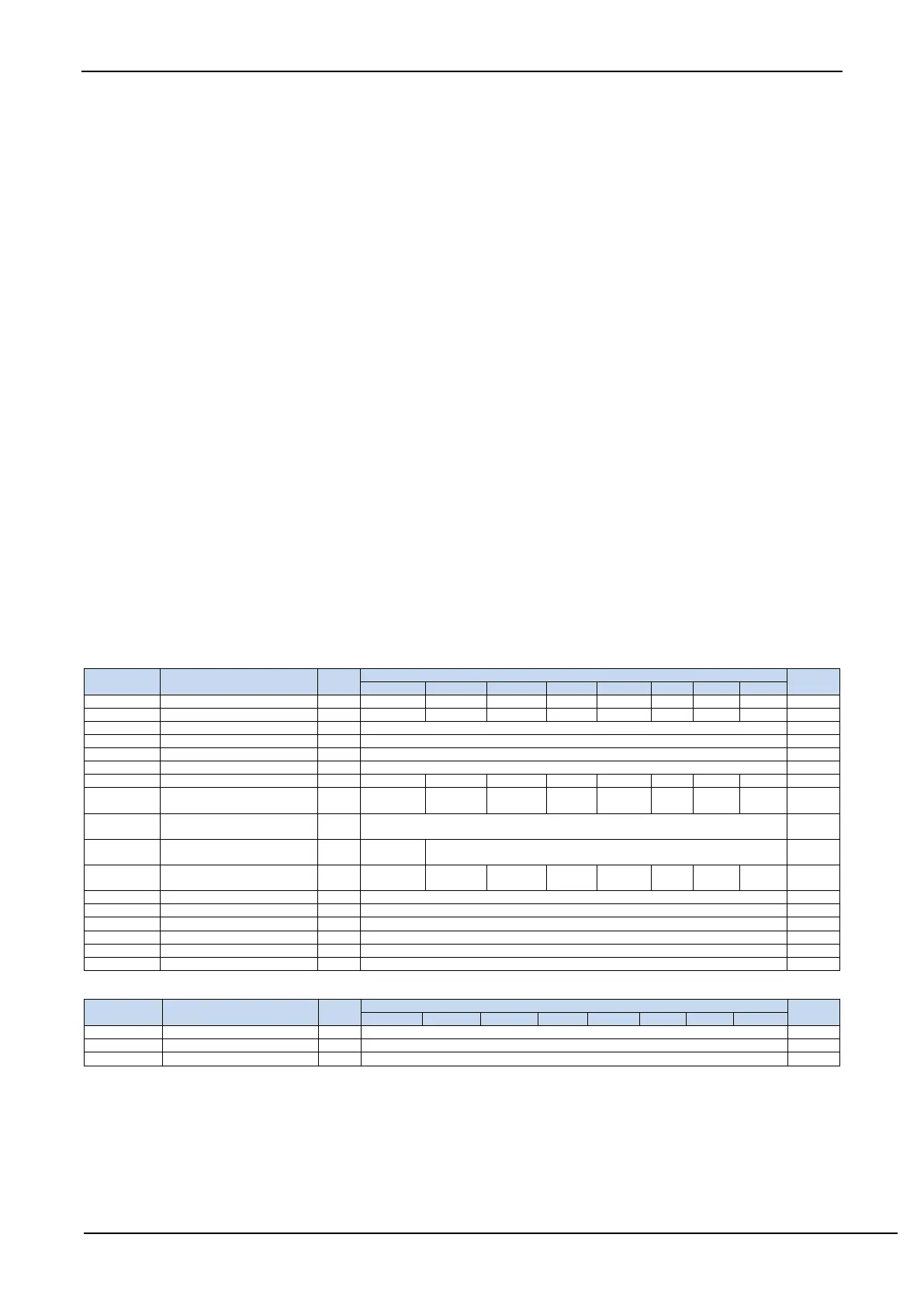
13.1 Registers Related to Timers
Timer 0 and 1 control register
Timer 0 and 1 mode register
Timer 0 low byte register
Timer 1 low byte register
Timer 0 high byte register
Timer 1 high byte register
External interrupt and clock output
control register
Wake-up Timer Control Register
low
Wake-up Timer Control Register
high byte
Timer4 and Timer 3 Control
Register
Timer 4 high byte register
Timer 4 low byte register
Timer 3 high byte register
Timer 3 low byte register
Timer 2 high byte register
Timer 2 low byte register
Timer 2 clock prescaler register
Timer 3 clock prescaler register
Timer 4 clock prescaler register