STC8A8K64D4 Series Manual
data transmitting pin, and RxD3 is the data receiving pin, the serial port is a full duplex receiver/transmitter.
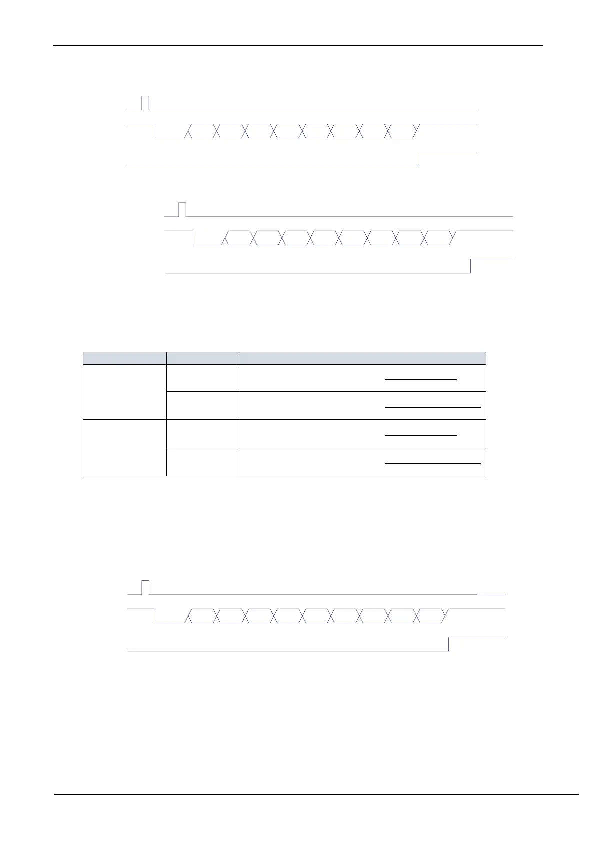
Write
S3BUF
TxD3
S3TI
D0 D1 D2 D3 D4 D5 D6 D7Start Stop
Transmitting data (UART3 mode 0)
Write
S3CON
RxD3
S3RI
D0 D1 D2 D3 D4 D5 D6 D7Start Stop
S3REN=1, S3RI=0
Receiving data (UART3 mode 0)
The baud rate of UART3 is variable. It is generated by T2 or T3. If the timer is in 1T mode (12x speed), the
corresponding baud rate is increased by 12 times.
The baud rate of UART3 mode 0 is calculated as follows, where SYSclk is the system operating frequency.
Baud rate calculation formula
14.5.4 UART3 Mode 1
UART3 operating in mode 1 is a 9-bit data UART mode with variable baud rate. One frame data consists of 11
bits: 1 start bit, 8 data bits (LSB first), 1 programmable bit (9
th
bit) and 1 stop bit. The baud rate is variable, which can
be set by the software as needed. TxD3 is the data transmitting pin, and RxD3 is the data receiving pin, the serial port
is a full duplex receiver/transmitter.
Write
S3BUF
TxD3
S3TI
D0 D1 D2 D3 D4 D5 D6 D7Start Stop
Transmitting data (UART3 mode 1)
TB8