Slavce mode, master mode with
notignoring SS and MSTR is 1. When SS
pin is pulled low, MSTR will be
automatically cleared by hardware and the
operating mode will be passively set to
slave mode.
Considerations for a Slave
When CPHA = 0, SSIG must be 0 (i.e. SS pin can not be ignored). The SS pin must be pulled low before each
serial byte begins transfer and must be reset to high after the transfer completes. The SPDAT register can not be written
while the SS pin is low, otherwise a write collision error will occur. Operation with CPHA = 0 and SSIG = 1 is undefined.
When CPHA = 1, SSIG may be set to 1 (i.e. the SS pin can be ignored). If SSIG = 0, the SS pin may remain active
low (i.e., stay low all the way) for consecutive transfers. This method is suitable for fixed single master single slave
system.
Considerations for a Master
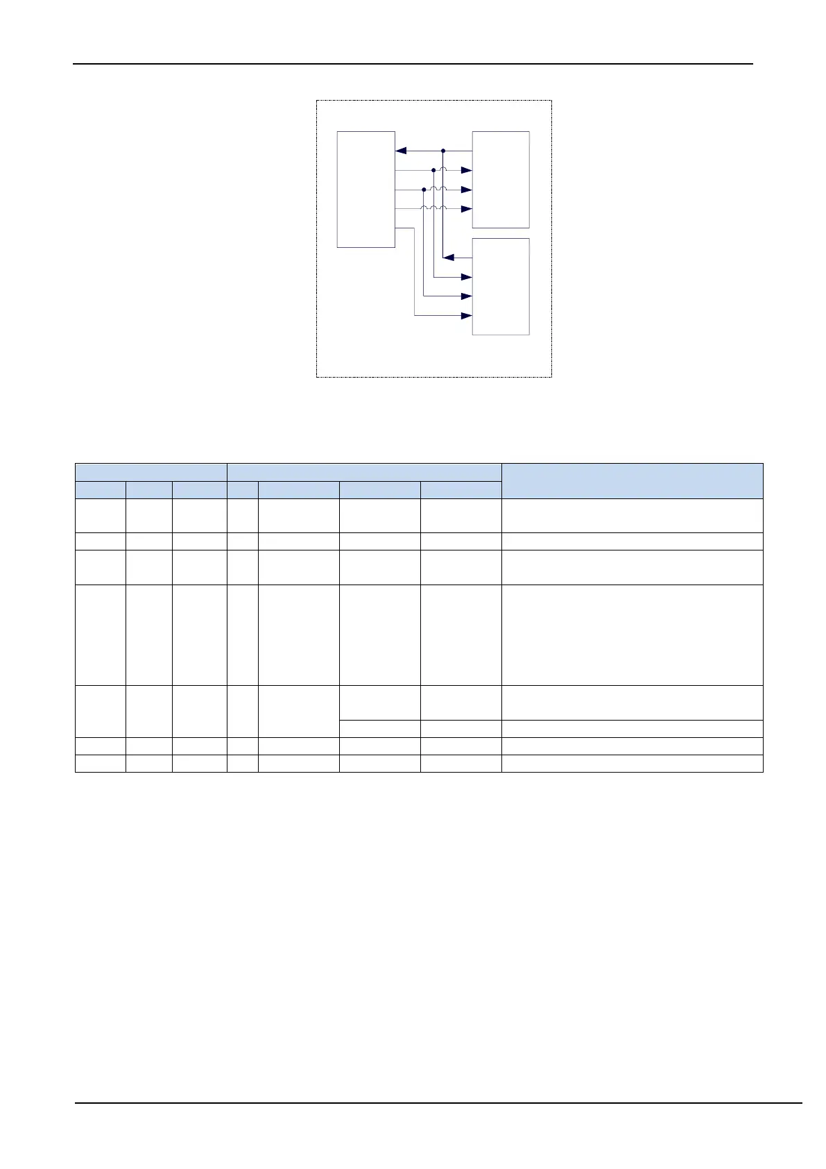
In SPI, transfers are always initiated by the master. If the SPI is enabled (SPEN = 1) and selected as the master,
the master will initiate SPI clock generator and data transfer by writing to SPI data register, SPDAT. The data will
appear on the MOSI pin a half to one SPI bit-time later after the data is written to SPDAT. The data written to the
SPDAT register of the master is shifted out from the MOSI pin and sent to the MOSI pin of the slave. And, at the same
time the data in SPDAT register of the selected slave is shifted out on MISO pin to the MISO pin of the master.
After one byte has been transmitted, the SPI clock generator is stopped, the transfer completion flag (SPIF) is set,
and an SPI interrupt is generated if the SPI interrupt is enabled. The two shift registers for the master and slave CPUs