STC8A8K64D4 Series Manual
Write
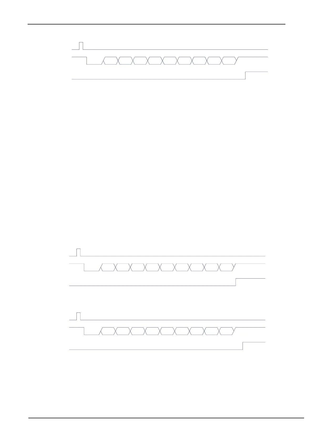
SCON
RxD
RI
D0 D1 D2 D3 D4 D5 D6 D7Start Stop
Receiving data (UART1 mode 2)
RB8
REN=1,RI=0
14.3.8 UART1 Mode 3
If the two bits of SM0 and SM1 are ‘11’, UART1 operates in mode 3. UART1 operating in mode 3 is a 9-bit data
asynchronous communication UART. One frame of data consists of 11 bits: 1 start bit, 8 data bits (LSB first), 1 programmable
bit ( 9
th
bit) and 1 stop bit. The transmitted programmable bit (9th bit) is supplied by TB8 in SCON, which can be confugred
as either 1 or 0 by software. Or, the odd/even parity bit P in the PSW can be loaded into TB8. Not only can TB8 be used as a
multi-machine communication address/data flag, but also it can be used as datum parity check bit. The 9
th
bit is received into
RB8 of SCON. TxD is the transmitting pin, and RxD is the receiving pin, the serial port is a full duplex receiver/transmitter.
Except that the 9
th
bit of the shift register supplied by TB8 while being sent is different, the functional and structure of
mode 3 and mode 1 are basically the same, the receiving / sending operation and timing of mode 3 and mode 1 are also
basically the same.
After the receiver receives a frame of information, the following conditions must be met at the same time.
·RI=0
·SM2=0 or SM2=1 and the 9
th
bit received RB8=1.
Only when the two conditions above are met at the same time, the data received in shift register is loaded into SBUF
and RB8. The RI flag is set to 1, and the interrupt is requested to CPU. If one of the above conditions is not met, the data
received in the shift register is invalid and is discarded, and RI is not set. Regardless of the above conditions are met or not,
the receiver begins to detect the RxD pin hopping information again to receive the next frame of information. In mode 3, the
received stop bit is not related to SBUF, RB8 and RI.
It provides for the convenience of multi-machine communication by setting SM2, TB8 of SCON and communication
protocol using the software.
Write
SBUF
TxD
TI
D0 D1 D2 D3 D4 D5 D6 D7Start Stop
Transmitting data (UART1 mode 3)
TB8
Write
SCON
RxD
RI
D0 D1 D2 D3 D4 D5 D6 D7Start Stop
Receiving data (UART1 mode 3)
RB8
REN=1,RI=0
The baud rate calculation formula of UART1 mode 3 is exactly the same as that of mode 1. Please refer to the
mode 1 baud rate calculation formula.