STC8A8K64D4 Series Manual
-
If one of the pin outputs logic “1” and the external device pulls it low, the weak pull-up transistor is off and the “very weak
pull-up” maintains on. To pull the pin low, the external device must have sufficient sink capability to make the voltage on the
pin drop below the threshold voltage. For a 5V microcontroller, the current of “weak pull-up” transistor is about 250uA; for
a 3.3V microcontroller, the current of “weak pull-up” transistor is about 150uA.
The second pull-up transistor, called “very weak pull-up”, turns on when the port latch is “1”. When the pin is not
connected, this very weak pull-up source produces a weak pull-up current that pulls the pin high. For a 5V microcontroller,
the current of “weak pull-up” transistor is about 18uA; for 3.3V microcontrollers, the current of “weak pull-up” transistor is
about 5uA.
The third pull-up transistor is called “strong pull-up”. This pull-up transistor is used to speed up the low-to-high transition
for quasi-bidirectional port pin when the port latch changes from logic “0” to logic “1”. When this occurs, the strong pull-up
transistor keeps on for about two clocks to quickly pull the pin high.
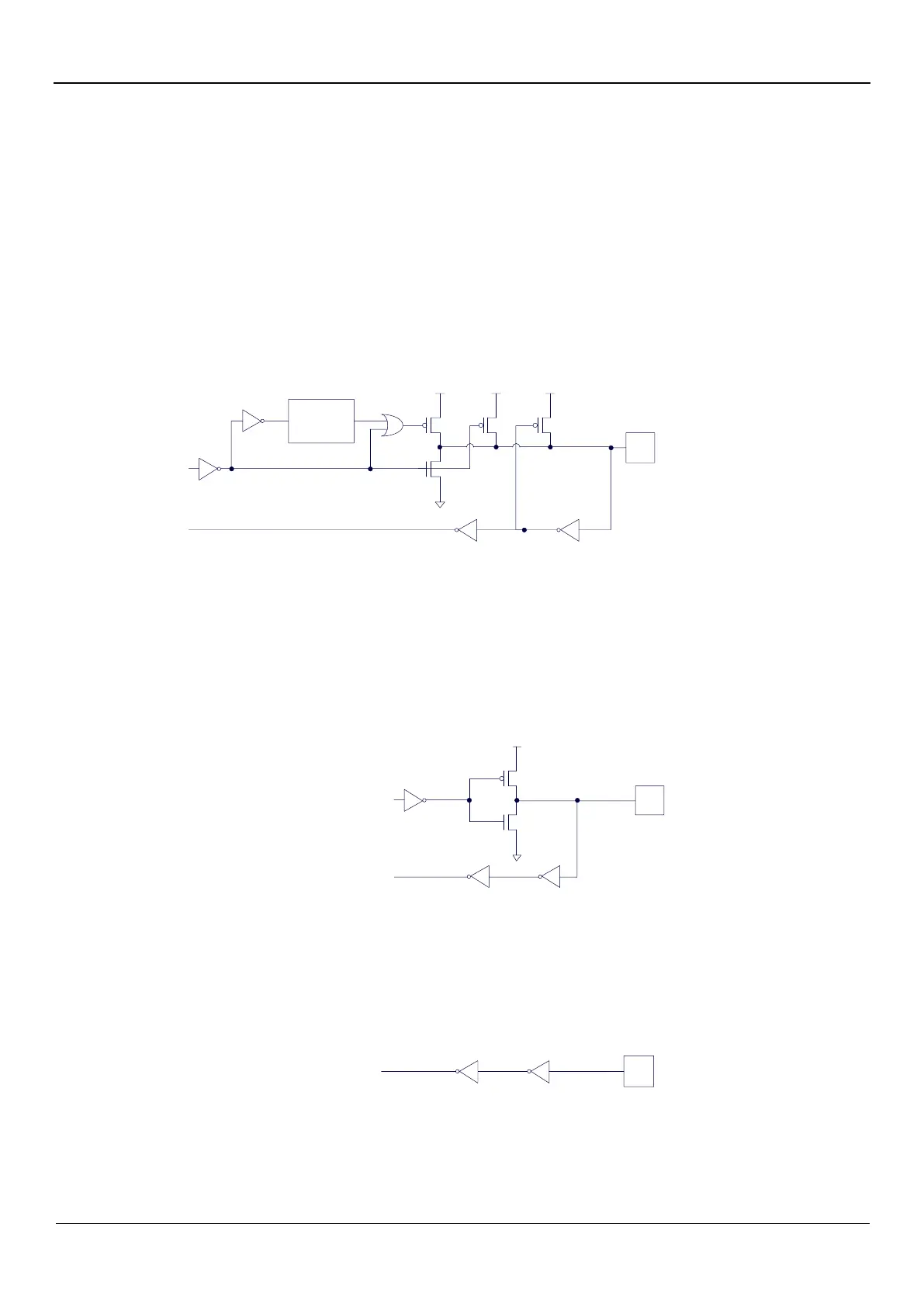
Quasi-bidirectional port (weak pull-up) has a Schmitt trigger and an interference suppression circuit. To read the correct
external state, quasi-bidirectional port (weak pull-up) should latch to ‘1’ before reading.
The structure of quasi-bidirectional port (weak pull-up) output is shown below:
Port latch data
2 clocks
delay
VCC
VCC
VCC
Input Data
Strong
Very
weak
Weak
Port
Pin
interference suppression
9.3.2 Push-Pull Output
The pull-down structure of the strong push-pull output mode is the same as the pull-down structure of the open-drain
output mode and quasi-bidirectional mode. However, the push-pull output mode can provide a sustained strong pull-up when
the latch is logic “1”. Push-pull mode is generally used when more drive current is required.
The structure of strong push-pull pin configuration is shown below:
Port latch data
VCC
Input Data
Strong
interference suppression
Port
Pin
9.3.3 High Impedance Input
The current can neither flow in nor flow out.
The input port has a Schmitt trigger input and an interference suppression circuit.
The structure of high impedance input pin configuration is shown below:
Input data
interference suppression
Port
Pin
9.3.4 Open-Drain Output
The open-drain mode can be used for both reading external status and 169utputting high or low level. To read the external
state correctly or output a high level, the external pull-up resistor should be connected.
All pull-up transistors are turned off in the open-drain output configuration when the port latch is logic “0”. There must