STC8A8K64D4 Series Manual
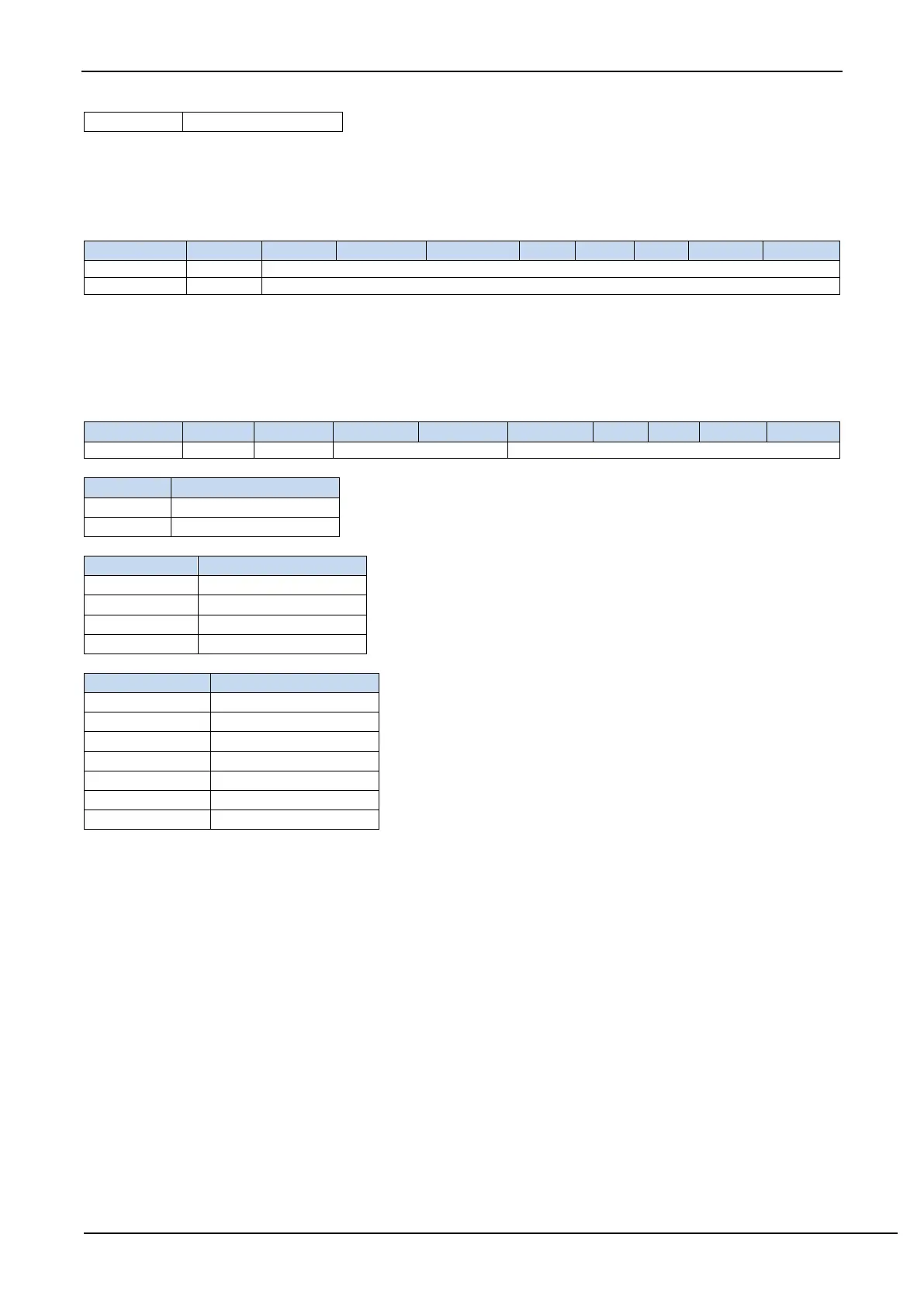
17.1.3 ADC result registers (ADC_RES, ADC_RESL)
After the A/D conversion is completed, the 10-bit/12-bit conversion result is automatically saved to ADC_RES
and ADC_RESL. Please refer to the RESFMT setting in the ADC_CFG register to see the result's data format.
17.1.4 ADC timing control register (ADCTIM)
CSSETUP: ADC channel selection time control T
setup
CSHOLD[1:0]: ADC Channel selection hold time control T
hold
SMPDUTY[4:0]: ADC analog signal sampling time control T
duty
(Note: SMPDUTY must not be set less than 01010B)
ADC digital-to-analog conversion time: T
convert
The conversion time of 10-bit ADC is fixed at 10 ADC working clocks
The conversion time of 12-bit ADC is fixed at 12 ADC working clocks
A complete ADC conversion time is: Tsetup + Tduty + Thold + Tconvert, as shown in the figure below