STC8A8K64D4 Series Manual
20 Sysnchronous Serial Peripheral Interface (SPI)
A high-speed serial communication interface, SPI, is integrated in STC8A8K64D4 series of microcontrollers. SPI
is a full-duplex high-speed synchronous communication bus. SPI interface integrated in the STC8A8K64D4 series of
microcontrollers offers two operation modes: master mode and slave mode.
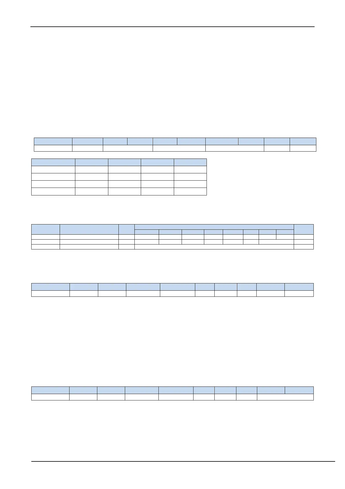
20.1 SPI function pin switch
SPI_S[1:0]: SPI function pin selection bit
20.2 Registers Related to SPI
20.2.1 SPI Status register (SPSTAT)
SPIF: SPI transfer completion flag.
When SPI completes sending / receiving 1 byte of data, the hardware will automatically set this bit and request
interrupt to CPU. If the SSIG bit is set to 0, this flag will also be automatically set by hardware to indicate a mode
change of device when the master / slave mode of the device changes due to changes in the SS pin level.
Note: This bit must be cleared using software writing 1 to it.
WCOL: SPI write collision flag bit.
This bit is set by hardware when the SPI is writing to the SPDAT register during data transfer.
Note: This bit must be cleared using software by writing 1 to it.
20.2.2 SPI Control Register (SPCTL)
SSIG: Control bit of whether SS pin is ignored or not.
0: the SS pin decides whether the device is a master or slave.
1: the function of SS pin is ignored. MSTR decides whether the device is a master or slave.
SPEN: SPI enable bit.
0: the SPI is disabled.
1: the SPI is enabled.