STC8A8K64D4 Series Manual
MOV P1.0,C ; Read comparator comparison result
JMP LOOP
END
15.4.3 Comparator is Used for External Power-down Detection (User data
should be saved to EEPROM in time during power down)
470u 104
P1.2
P1.3
P1.4
P1.5
P1.6
P1.7
P5.4
Vcc
P5.5
Gnd
P1.1
P1.0
CMP+ / P3.7
CMP- / P3.6
P3.5
P3.4
P3.3
P3.2
P3.1
P3.0
1
2
3
4
5
6
7
8
9
10
20
19
18
17
16
15
14
13
12
11
STC8G1K08
Vcc
R1
100K
or greater
7805
R2
?
Vin
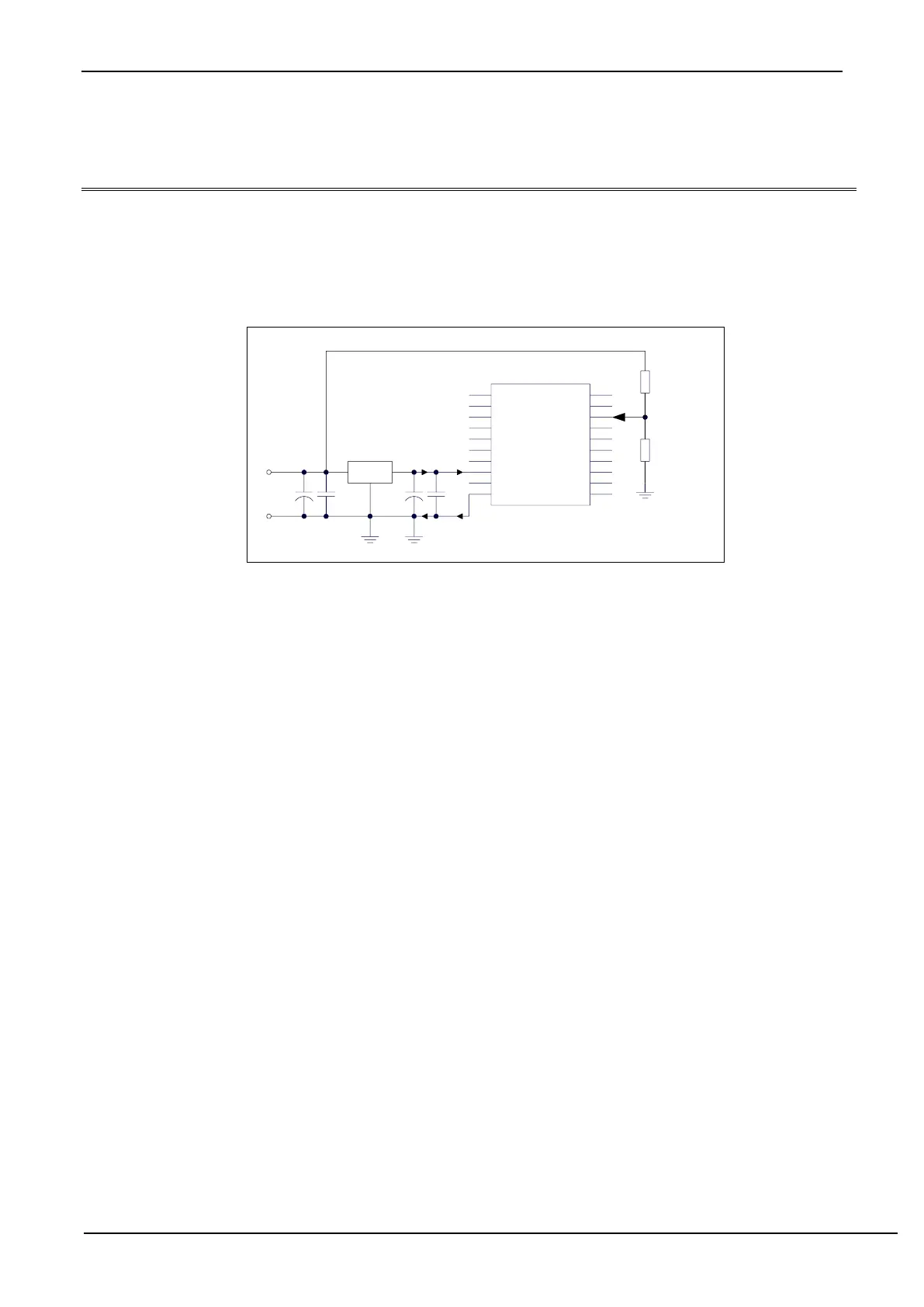
In the figure above, the resistor R1 and R2 divide the front-end voltage of the voltage regulator 7805. The divided
voltage is used as the external input of the comparator CMP+ to compare with the internal reference voltage.
When the AC power is at 220V, the DC voltage at the front end of the voltage regulator block 7805 is 11V, and
when the AC voltage drops to 160V, the DC voltage at the front end of the voltage regulator 7805 is 8.5V. When the dc
voltage at the front end of the voltage regulator 7805 is lower than or equal to 8.5V, the dc voltage at the front end is
divided by the resistors R1 and R2, and added to the comparator positive input terminal CMP+. The input voltage at
the CMP+ terminal is lower than the internal reference voltage. A comparator interrupt can be generated at this time,
so that there is sufficient time to save the data to the EEPROM during power-down detection. When the DC voltage of
the front end of the voltage regulator 7805 is higher than 8.5V, the DC voltage input by the front end is divided by the
resistors R1 and R2, and connected to the comparator positive input terminal CMP+. The input voltage of the CMP+
terminal is higher than the internal reference voltage. At this time, the CPU Can continue to work normally.
The internal reference voltage is the REPV of the internal BandGap after the amplified (the internal reference
voltage is adjusted to 1.19V when the chip is shipped from the factory). The specific value should be obtained by
reading the value occupied by the internal reference voltage in the internal RAM area or the Flash program memory
(ROM) area. For STC8 series, the storage address of the internal reference voltage value in RAM and Flash program
memory (ROM), please refer to the Chapter of "Special Parameters in Memory".