STC8A8K64D4 Series Manual
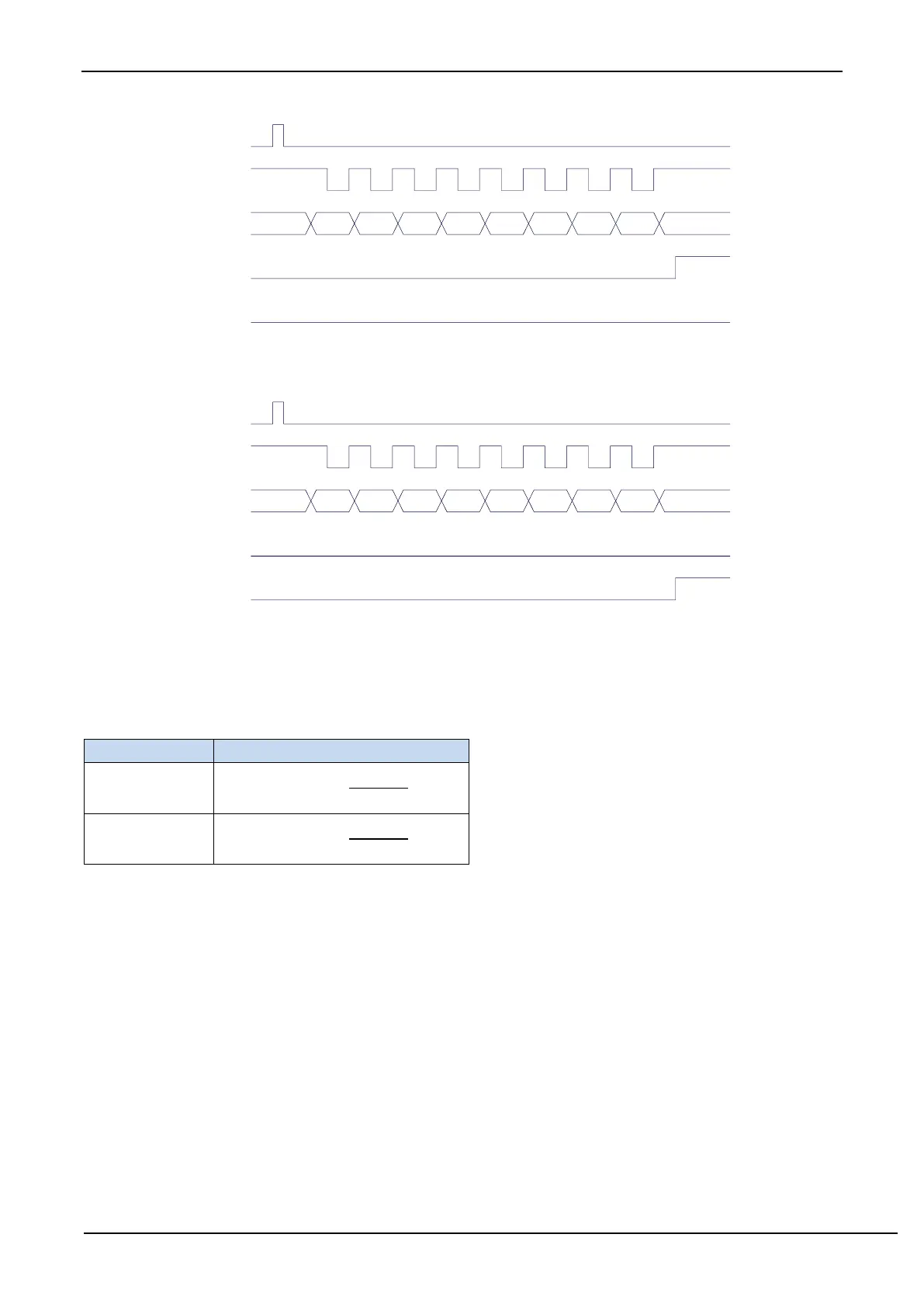
Write
SBUF
TxD
RxD
TI
RI
D0 D1 D2 D3 D4 D5 D6 D7
Transmitting data (UART1 mode 0)
Write
SCON
TxD
RxD
TI
RI
D0 D1 D2 D3 D4 D5 D6 D7
REN=1, RI=0
Receiving data (UART1 mode 0)
In mode 0, SM2 must be cleared so that TB8 and RB8 bits are not affected. Since the baud rate is fixed at SYSclk/12 or
SYSclk/2, no timer is required and the clock of the microcontroller is used as the synchronous shift pulse directly.
The baud rates of UART1 mode 0 are shown in the following table, where SYSclk is the system operating frequency:
Baud rate calculation formula
14.3.6 UART1 Mode 1
If SM0 and SM1 of SCON are set to ‘01’ by the software, UART1 will work in mode 1, which is a 8-bit UART mode.
In mode 1, a frame of information consists 10 bits: 1 start bit, 8 data bits (LSB first) and 1 stop bit. The baud rate is variable,
which can be set by the software as needed. TxD is the data transmitting pin, and RxD is the data receiving pin, the UART is
a full duplex receiver/transmitter.
Transmission process of mode 1: TxD is used as data output pin when transmitting a datum. Transmission is initiated by
writing SBUF. "1" is also written into the 9
th
bit of transmission shift register by the writing "SBUF" signal, and the TX
control unit is notified to start sending. The shift register shifts the data right to TxD to send, and shifts "0" in the left to
supplement. When the highest bit of data is shifted to the output of the shift register, it is followed by the 9
th
bit "1", and all
bits to the left of it are "0". This state causes the TX control unit to make the last shift output, and then disables the transmission
signal "SEND" to complete the transmission of a frame and sets TI, and requests interrupt processing to CPU.
Receiving process of mode 1: After the software sets the reception enable flag REN, i.e. REN = 1, the receiver will
detect the RxD pin signal. The receiver is ready to receive data when a "1" → "0" falling edge is detected at RxD pin, and