STC8A8K64D4 Series Manual
resets the receiving counter of the baud rate generator immediately, loads 1FFH into the shift register. The received datum is
shifted in from the right of the receiving shift register, the loaded 1FFH is shifted out to the left. When the start bit "0" is
shifted to the far left of the shift register, the RX controller shifts for the last time and completes a frame receiving. The
received datum is valid only if the following two conditions are met:
·RI=0;
·SM2=0 or the stop bit received is 1.
The datum received is loaded into SBUF, the stop bit is loaded into RB8, RI flag is set to request interrupt to CPU. If
the two conditions can not be met at the same time, the received data is invalid and is discarded. Regardless of the conditions
are met or not, the receiver will re-test RxD pin of the "1" → "0" edge, and continue to receive the next frame. If the received
datum is valid, the RI flag must be cleared by software in the interrupt service routine. Usually, SM2 is set to "0" when serial
port is operating in mode 1.
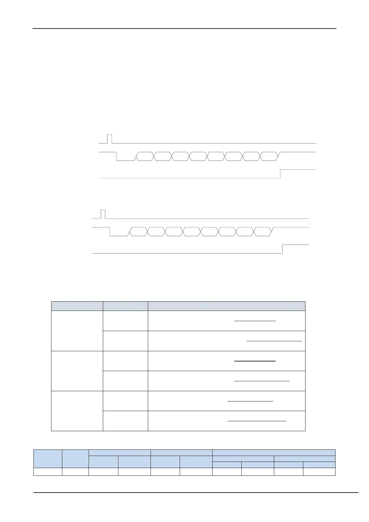
Write
SBUF
TxD
TI
D0 D1 D2 D3 D4 D5 D6 D7Start Stop
Transmitting data (UART1 mode 1)
Write
SCON
RxD
RI
D0 D1 D2 D3 D4 D5 D6 D7Start Stop
REN=1, RI=0
Receiving data (UART1 mode 1)
The baud rate of UART1 is variable. It can be generated by T1 or T2. If the timer is in 1T mode (12x speed), the
corresponding baud rate is increased by 12 times.
The baud rate of UART1 mode 1 is calculated as follows, where SYSclk is the system operating frequency.
Baud rate calculation formula
reloadvalueofT2 65536
SYSclk
4 baudrate
reloadvalueoftimer2 65536
SYSclk
12 4 baudrate
reloadvalueofT1 65536
SYSclk
4 baudrate
reloadvalueofT1 65536
SYSclk
12 4 baudrate
reloadvalueofT1 256
2
SYSclk
32 baudrate
reloadvalueofT1 256
2
SYSclk
12 32 baudrate
The reload value of the timers corresponding to the common frequency and the common baud rate are as following.