STC8A8K64D4 Series Manual
Multiplier: {MD5,MD4}
Product: {MD3,MD2,MD1,MD0}
32-bit logical shift left / logical shift right
Operand: {MD3,MD2,MD1,MD0}
32-bit data normalization:
Operand: {MD3,MD2,MD1,MD0}
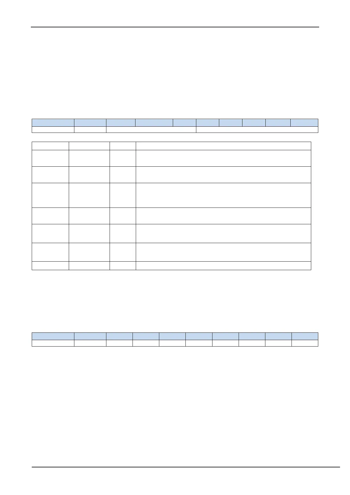
25.1.3 MDU Mode Control Register (ARCON)
MODE[2:0]: MDU mode selection
Shift the data in {MD3, MD2, MD1, MD0} right by SC [4: 0] bits,
MD3 high-order complement 0
Shift the data in {MD3, MD2, MD1, MD0} SC [4: 0] bits to the left,
low-order complement of MD0
Perform logical left shift on the data in {MD3, MD2, MD1, MD0},
shift out all the high-order 0s of the data, make the highest bit of MD3
be 1, and the number of logical left shifts is recorded in SC [4: 0].
{MD1,MD0
}×
{MD5,MD4}
=
{MD3,MD2,MD1,MD0}
{MD1,MD0
}÷
{MD5,MD4}
=
{MD1,MD0}
…
{MD5,MD4}
{MD3,MD2,MD1,MD0
}÷
{MD5,MD4}
=
{MD3,MD2,MD1,MD0}
…
{MD5,MD4}
SC[4:0]: Data shift bits
When the MDU is in shift mode, SC is used to set the number of bits for left/right shift
When MDU is in data normalization mode, SC is the actual number of bits moved by the data after data
normalization
25.1.4 MDU Operation Control Register (OPCON)
MDOV: MDU
Overflow flag (read-only flag)
MDOV is set by hardware automatically in the following situations:
1. When the divisor is 0;
2. When the product of multiplication is greater than 0FFFFH;
When software writes OPCON.0 (EN) or writes ARCON, MDOV is cleared by the hardware automatically.
RST: Software resets the MDU multiplication and division unit. Writing 1 to it will trigger a software reset. It is
cleared by the hardware automatically after the MDU reset is complete.
Note: The value of the ARCON register is cleared when software resets the MDU multiply and divide unit.
ENOP: MDU enable bit.
Writing 1 to this bit will trigger the MDU module to start calculation. When the MDU calculation is completed,
ENOP is cleared to 0 by the hardware automatically. After setting ENOP to 1, the software can query ENOP
cyclically. When ENOP changes from 1 to 0, the calculation is completed.