18.3.4.4 10-bit PWM Mode
When EBSn [1: 0] in the PCA_PWMn register is set to 11, PCAn operates in 10-bit PWM mode, where
{CH[1:0],CL[7:0]} is compared with the capture registers{EPCnL,XCCAPnL[1:0],CCAPnL[7:0]}. When PCA
modules are operating in 10-bit PWM mode, the output frequencies of them are the same because all the modules share
a single PCA counter. The output duty ratio of each module is set using the registers {EPCnL,
XCCAPnL[1:0],CCAPnL[7:0]}. The output is low when the value of {CH[1:0],CL[7:0]} is less than
{EPCnL,XCCAPnL[1:0],CCAPnL[7:0]}, and the output is high when the value of {CH[1:0],CL[7:0]} is equal to or
greater than {EPCnL,XCCAPnL[1:0],CCAPnL[7:0]}. When {CH[1:0],CL[7:0]} overflows from 3FF to 00, the
contents of {EPCnH,XCCAPnH[1:0],CCAPnH[7:0]} are reloaded into {EPCnL,XCCAPnL[1:0], CCAPnL[7:0]}. This
makes it possible to update the PWM without interference.
PWM frequency in 10-bit mode =
PCA input clock source frequency
1024
When EPCnH=0 and CCAPnH=00H, PWM fixed output high
When EPCnH=1 and CCAPnH=FFH, PWM fixed output low
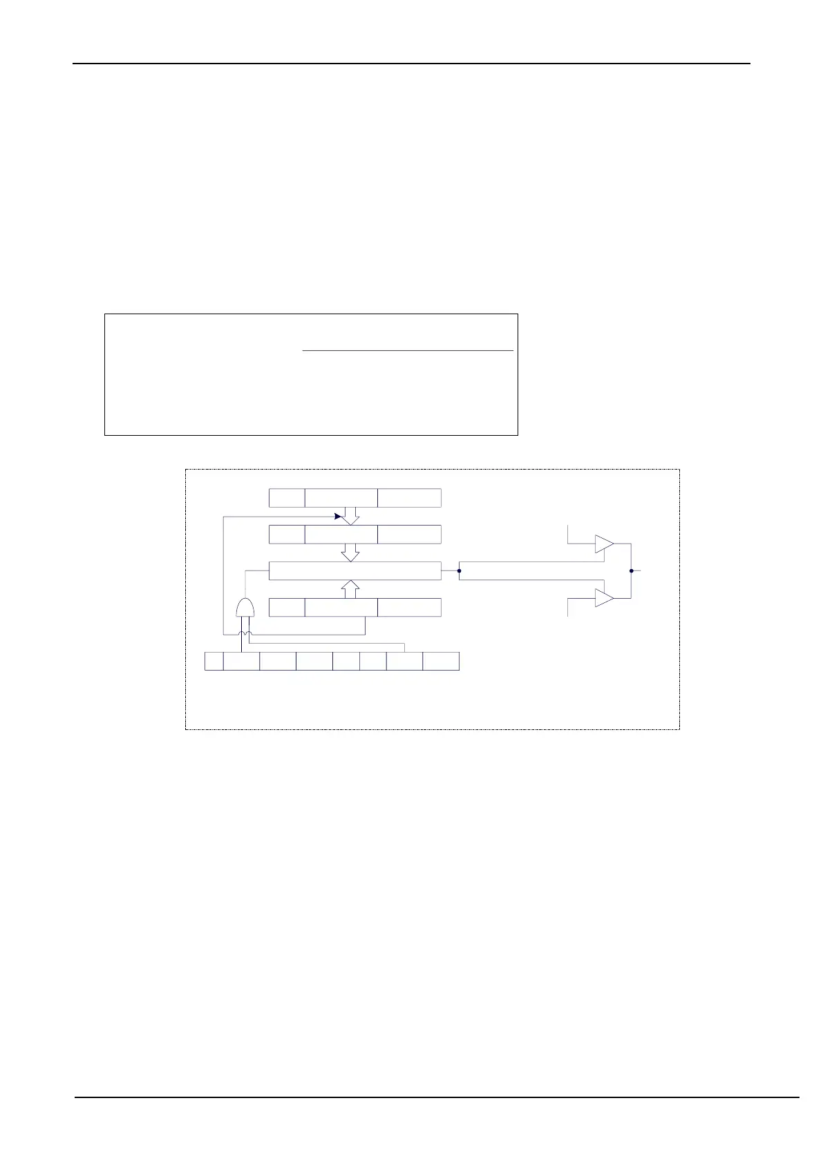
PCA 10-bit PWM mode
0 0 0
Output 0
0 0
11-bit comparator
enable
CL overflow
CCPn
1
reload
CCAPMn
- ECOMn CAPPn CAPNn MATn TOGn PWMn ECCFn
Output 1
{0,CH[1:0],CL[7:0]}<{EPCnL,XCCAPnL[1:0],CCAPnL[7:0]}
{0,CH[1:0],CL[7:0]}>={EPCnL,XCCAPnL[1:0],CCAPnL[7:0]}
EPCnH XCCAPnH[1:0] CCAPnH[7:0]
EPCnL XCCAPnL[1:0] CCAPnL[7:0]
0 CH[1:0] CL[7:0]
18.3.4.5 How to control PWM fixed output high / low
If PCA_PWMn &= 0xC0 and CCAPnH = 0x00, PWM fixed output high.
If PCA_PWMn |= 0x3F and CCAPnH = 0xFF, PWM fixed output low.