STC8A8K64D4 Series Manual
0001: START command. Send a START signal. If the I
2
C controller is in idle state currently, i.e. MSBUSY
(I2CMSST.7) is 0, writing this command will make the controller enter the busy status, and the hardware will
set the MSBUSY status bit automatically and start sending START signal. If the I
2
C controller is busy
currently, writing this command will triger to send the START signal. Sending the START signal waveform
is shown below:
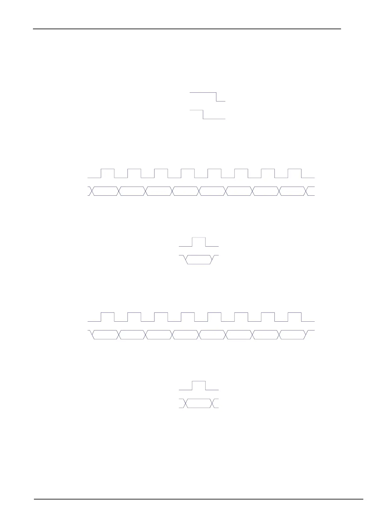
0010: Send data command.
After writing this command, the I
2
C bus controller will generate 8 clocks on the SCL pin and send the data
in the I2CTXD register bit by bit to the SDA pin (send MSB firstly). The waveform of the transmitting data
is shown in the following figure:
SCL
D7 D6 D5 D4 D3 D2 D1 D0
SDA
(output)
0011: Receive ACK command.
After writing this command, the I
2
C bus controller will generate a clock on the SCL pin and save the data
bit read from SDA to MSACKI (I2CMSST.1). The waveform of the receiving ACK is shown below:
0100: Receive data command.
After writing this command, the I
2
C bus controller will generate 8 clocks on the SCL pin, and sequentially shift
the data bit read from SDA to the I2CRXD register (receiving MSB firstly). The waveform of the receiving data
is as shown in the figure below:
SCL
D7 D6 D5 D4 D3 D2 D1 D0
SDA
(input)
0101: Send ACK command.
After writing this command, the I
2
C bus controller will generate a clock on the SCL pin and send the data
bit in MSACKO (I2CMSST.0) to SDA. The waveform of sending ACK is shown below:
0110: Send STOP signal.
After writing this command, the I
2
C bus controller starts sending STOP signal. After the signal is sent, the
hardware clears the MSBUSY status bit automatically. The waveform of STOP signal is shown below: