OnAir 2500/OnAir 3000 Digital Mixing Consoles
Conguration 6-5
Date printed: 22.07.08
SW V3.0
6.1.1.6 Logical Outputs
Output Mapping In order to start the mapping at a clearly dened initial position, auto con-
guration rst clears any existing output mapping. It also makes sure that no
HD outputs are used for I/O sharing physical connections, and that the net
type of all HD outputs is cleared. Then it detects all output cards installed in
the D21m frame(s) connected to the DSP card and maps the physical output
signals to the logical outputs according to the following rules:
• Line output cards are mapped to 4 stereo logical outputs
• AES/EBU I/O cards are mapped to 8 stereo logical outputs
• * Further ADAT I/O cards are mapped to 2 × 8 mono logical outputs
• * TDIF I/O cards are mapped to 2 × 8 mono logical outputs
• MADI I/O cards are mapped to up to 64 mono logical inputs, depending
on the DIP switch setting on the card
• ** SDI I/O cards are mapped to 8 mono logical outputs.
• ** Dolby E input cards are mapped to either 4 or 8 mono logical outputs,
depending on the number of Dolby E decoders installed on the card (the
logical outputs of a Dolby E input card may be used as decoder inputs from
the backplane side).
• * CobraNet
®
I/O cards
• * Ethersound
®
I/O cards
• * Aviom A-Net
®
output cards.
* OnAir 2500: In external I/O frame only. ** OnAir 3000 only.
Label The eight-character labels are generated according to the same rules given in
chapter 6.1.1.1.
6.1.1.7 Patch Outputs (supported by OnAir 3000 only)
Patch outputs are not initialized by auto conguration; they have to be con-
gured manually later.
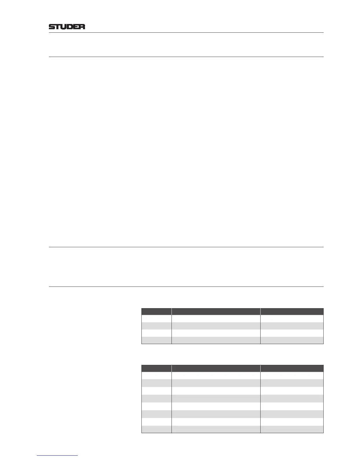
6.1.1.8 Output Routing
Logical outputs connected to the rst line I/O card (if available in the system)
are routed to the following summing buses:
Connector Signal Output Type
1 / 2
PRG A
Logical Stereo
3 / 4
PRG B (OnAir 3000 only) Logical Stereo
5 / 6
RECORD Logical Stereo
7 / 8
AUX 1 Logical Stereo
Logical outputs connected to the rst AES/EBU I/O card (if available in the
system) are routed to the following summing buses:
Connector Signal Output Type
1
PRG A
Logical Stereo
2
PRG B (OnAir 3000 only) Logical Stereo
3
RECORD Logical Stereo
4
AUX 1 Logical Stereo
5
AUX 2 Logical Stereo
6
AUX 3 Logical Stereo
7
AUX 4 Logical Stereo
8
N–X 1 Logical Stereo
 Loading...


