Date printed: 22.07.08
4.3 System Power
Power Supply The console is equipped with an autoranging primary power supply unit
(input voltage range 80...240 V
AC
/50...60 Hz) with power factor correction.
The mains switch is located at the rear, next to the power inlet.
The OnAir 2500 is EN and UL approved.
Redundancy The console can be equipped with a second, external 1U power supply unit for
redundancy., supplying 24 V
DC
input in addition to the mains power inlet.
UPS For extra safety against line loss cases, supplying the console by an UPS (un-
interruptible power supply) is recommended.
The desk is normally switched on and off with the studio master mains switch;
it may be switched on and off also with its own mains switch, with the one
of the external PSU, or with both (depending on the system configuration)
without any audio signals or audio parameters getting lost.
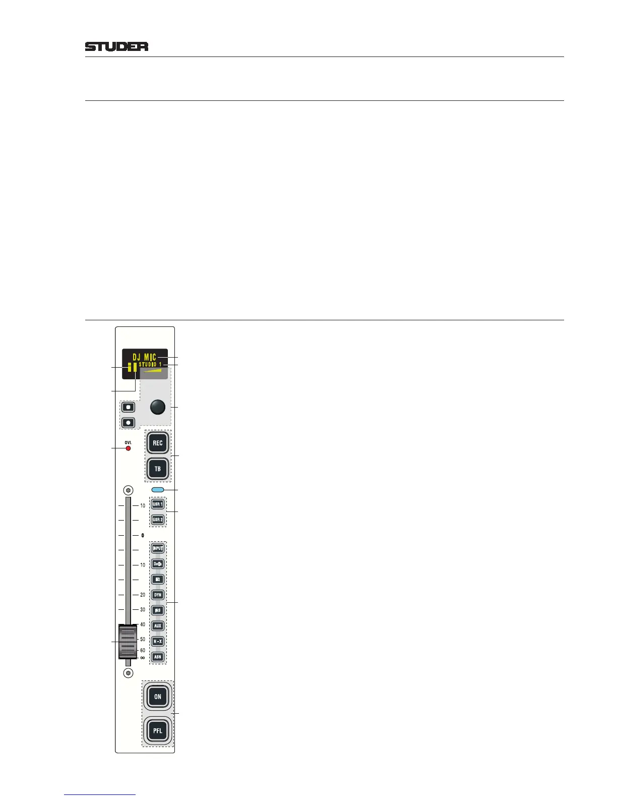
4.4 Fader Module
The fader module contains six fader strips (only one of them shown in the
illustration on the left). Up to four fader modules can be combined, giving
the maximum configuration for a 24-channel desk.
The fader strip has been designed with as few operating elements as possible.
All other functions are available through the configurable user keys or on the
central touch-screen.
Every fader strip contains four large, configurable keys, the fader (motor fader
optional), a channel-active indicator (illuminated if: channel is ON, fader
is open, channel is assigned to a main output, and master fader is open), a
rotary encoder and associated keys, an overload LED and an graphical OLED
channel label display. For direct access to the most used functions, the direct
access keys are available. After pressing one of them, parameters can now be
entered on the central touch screen, either by the rotary encoders (e.g. input
selection or gain) or by the corresponding buttons (e.g. EQ on/off). The new
settings are immediately visible on the central screen.
The large keys as well as the user keys can be freely configured and assigned,
and the large keys have transparent snap-on caps for convenient labeling. This
allows for example to have ON and OFF keys at the lower end of the channel
strip if required, or to assign a different function to the TB key if the source
is e.g. a CD player. These settings are input source-related and will automati-
cally follow the source in case the routing is changed.
ON Pressing the key toggles the channel on/off function. In the audio path, the
on/off switch is located after fader and panning.
On status is indicated by illuminating the key.
The function is disabled when the corresponding fader is configured as master
fader for a certain bus.
¹ PFL The purpose of PFL is to feed the pre-fader audio signal of the desired channel
or AUX send, group, or master (program, record) to the PFL bus. If active,
the key is illuminated in yellow.
If the “PFL Cut on Channel Active” function (also referred to as “broadcast
PFL mode”) is enabled, audio signals are temporarily cut from the PFL bus
as long as the channel is ON and the fader is open. In such a case the PFL key
is illuminated in amber.