OnAir 2500 Digital Mixing Console
Operation 5-53
Date printed: 18.07.08
SW V3.0
CHAN - FDR Bus Page
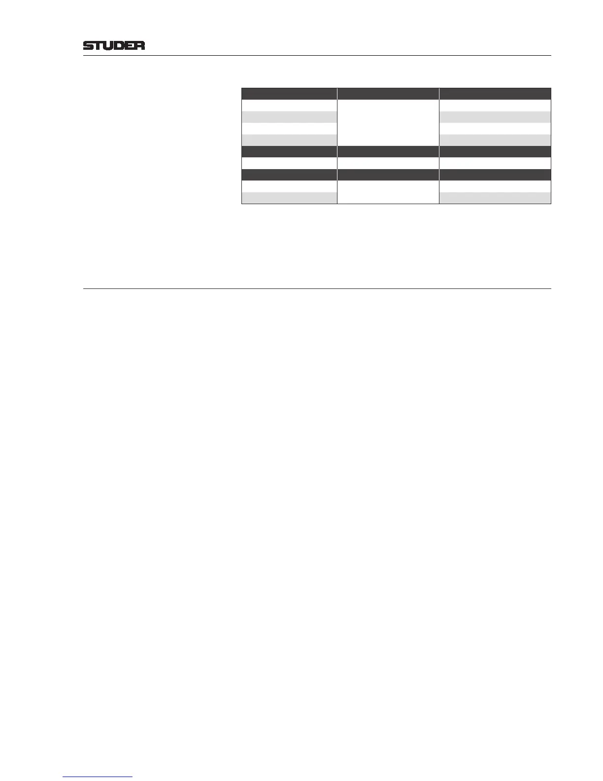
Joker Button*:
TB Status Joker Button Function Joker Button Indication
Off
TALK or PFL/TALK
Dark
On Yellow
Programming TB group Yellow if assigned to group
Cut Yellow
- Joker Button Function Joker Button Indication
- PFL/LOC Always dark
Ready Status Joker Button Function Joker Button Indication
Off
LOC/RDY
Dark
On Yellow
* On the CHAN - FDR Bus page, the Joker button never indicates the PFL
status since the page contains a dedicated PFL button.
5.6 Signaling
The OnAir 2500 has full-way red light signaling, which means that the audio
path must be open from the microphone to the master output in order that
red light indication becomes active. Signaling settings are performed in the
configuration tool.
Signaling is provided for control room and studio; it works with the config-
ured behavior of the inputs describing the microphone locations. Red light
indication in the control room is provided in the monitoring/TB part of the
central module and in the central screen. Possible locations are CR (control
room) and ST (studio).
The ON AIR indication may be AND-linked with an external signal, e.g. com-
ing from the master control room, indicating that the signal is actually routed
to the antenna (see GPIO section). It is configurable which main master (or
which combination of them) activates the ON AIR indication.
Example Red light indication for a particular location is active if:
• at least one microphone input in this location is routed to a channel,
AND
• this channel’s fader is open, the channel is switched ON and is routed to a
main master,
AND
• this main master’s fader (if configured) is open.