OnAir 2500 Digital Mixing Console
Operation 5-15
Date printed: 18.07.08
SW V3.0
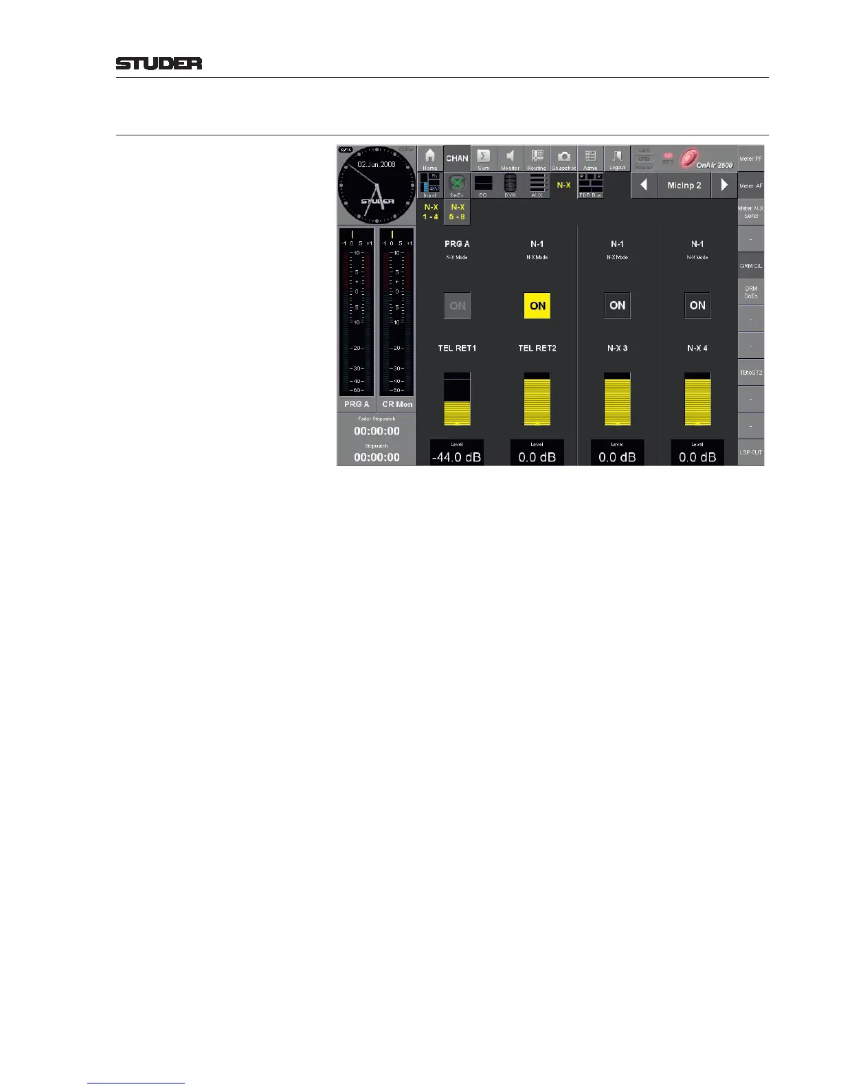
5.3.3.6 (Channel) N–X Page
N–X Mode This is an indication on which main output assignment the channel’s contribu-
tion to the N–X bus depends (PRG A or REC), or whether the bus is used
as AUX bus (AF or PF); in the latter case, its control elements are displayed
in orange as usual for an AUX bus. This assignment is performed on the Sum
- N–X pages (see chapter 5.3.4.3). The “classical” N–1 mode can be activated
there as well.
ON On/off control for the channel’s contribution to the individual N–X buses;
highlighted if on.
Level The channel’s contribution level to the individual N–X buses is indicated by
the yellow-colored bar graph. Its value is displayed in dB and can be set with
the rotary encoder below the field or on the channel strip. Maximum setting
is +12 dB.