OnAir 2500 Digital Mixing Console
Operation 5-11
Date printed: 18.07.08
SW V3.0
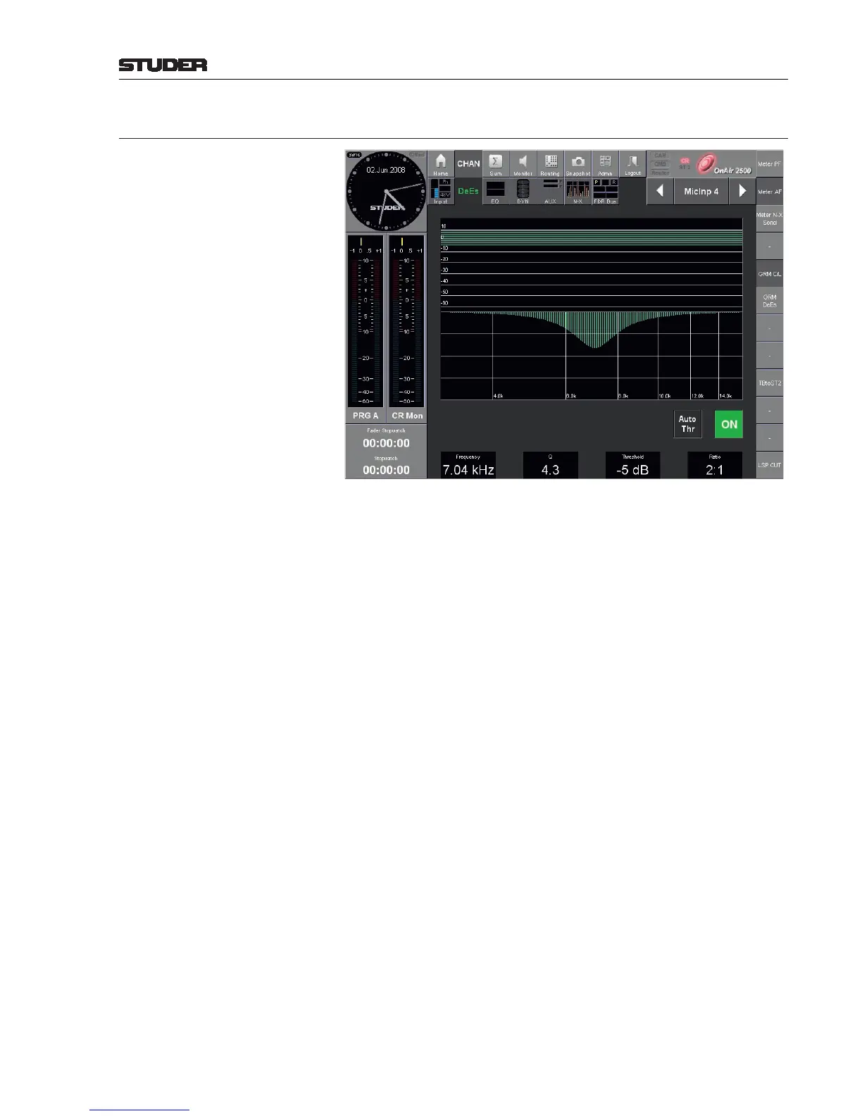
5.3.3.2 (Channel) De-Esser Page
Each channel has an integrated de-esser. This is a dynamically controlled
filter, normally used to reduce the “s” components of a microphone signal.
The filter range is placed over the signal’s “s” frequency components; if an
“s” component is detected in the audio signal, the level within the filter range
is dynamically reduced.
Graph The lower green graph represents the current, static filter curve of the de-es-
ser. The horizontal axis represents the log. frequency, while the vertical axis
represents the de-esser’s attenuation. Please note that this is a static indication
only, intended to give you an idea of the current filter settings. The actual at-
tenuation in the selected range depends on the current signal level, combined
with the Threshold and Ratio settings.
The upper green graph indicates the current Threshold setting.
ON Button to enable/disable the de-esser section of this channel; highlighted if
on.
Auto Thr Automatic threshold setting depending on the current signal content. If Auto
Thr is on, the button is highlighted and the threshold graph turns gray.
Frequency Center frequency of the de-esser’s filter band. It is indicated in Hz and can be
set with the rotary encoder below the field in a 4...10 kHz range.
Q Q factor (bandwidth) of the filter. It is indicated as a plain number and can be
set with the rotary encoder below the field in a range of Q = 0.27 (wide) to
8.7 (narrow).
Threshold The threshold is the audio signal level above which the de-esser starts to act
within the adjusted filter band. It is displayed in dB and can be set with the
rotary encoder below the field in a 96 dB range.
Ratio Level reduction ratio within the filter range, if an “s” component is detected
in the audio signal. This can be set with the rotary encoder below the field in
a range of 1:1 (no effect) through 20:1 (heavy de-essing).