Notes The ñ/Shift and Caps Lock functions of screen and USB keyboards are
independent. In addition, the external keyboard usually supports more char-
acters than the one on the central screen.
These two facts are of particular importance when entering user passwords:
Make sure that the upper/lower case setting of the USB keyboard is correct.
Be careful not to use any special characters that the user has not available
on the central screen keyboard.
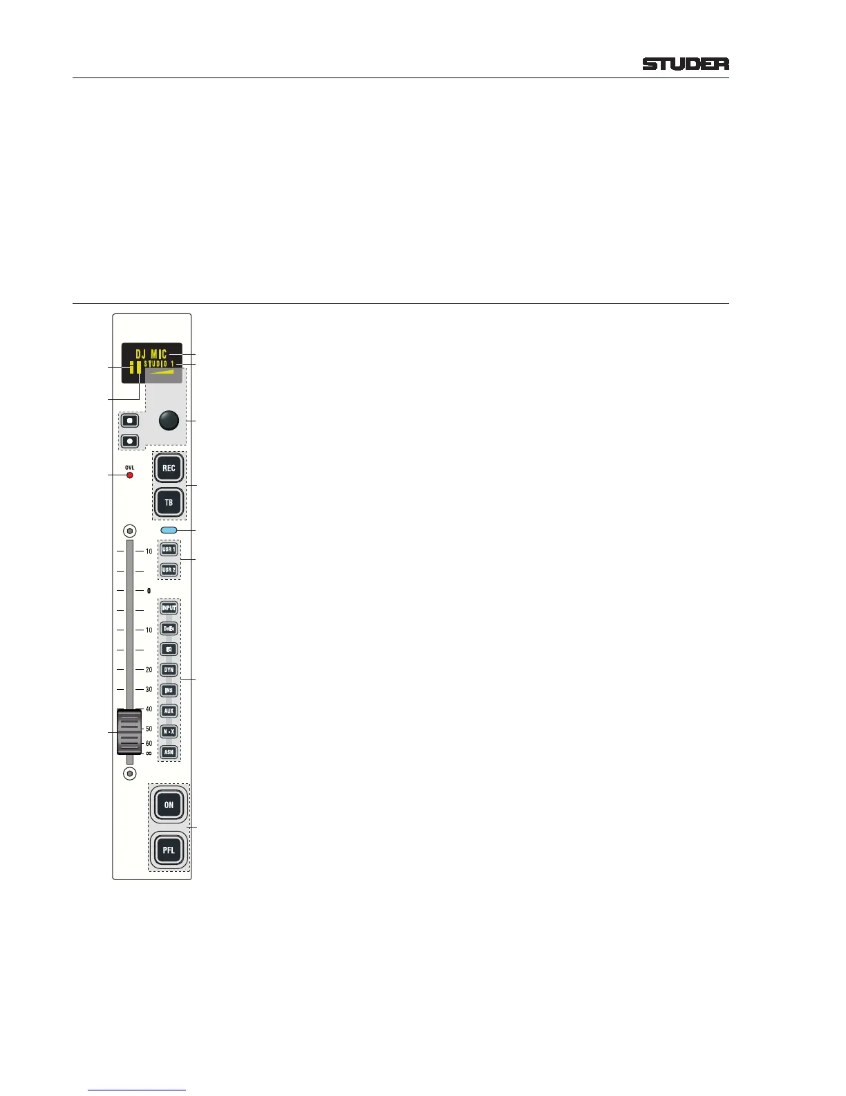
5.2 Direct Access Keys
Pressing, for example, the INPUT key will open the channel control page of
the corresponding channel on the central screen.
The most important settings for this channel are indicated on the channel
strip’s OLED display as well.
Depending on the access permission of the currently logged-in user (refer to
chapter 5.10), functions that are not available to this user will not open the
corresponding page on the central screen.
INPUT Pressing the INPUT key will open the channel page on the central screen.
Parameters can be entered or modified there.
The horizontal bar graph represents the gain or calibration value.
The input status is indicated in the text field (for details refer to chapter 5.3.3.1,
Channel Input Page).
DeEs Pressing DeEs opens the Channel De-Esser page on the central screen; the
EQ Pressing EQ opens the Channel Equalizer page on the central screen.
Parameters can be entered or modified there.
DYN Pressing this key opens the Channel Dynamics page on the central screen.
Parameters can be entered or modified there.
INS Pressing this key opens the Routing Insert page on the central screen for as-
signing one of the inserts out of the insert pool to this channel. The insert send
is always active.
AUX Pressing this key opens the Channel AUX page on the central screen for enter-
ing or modifying parameters. If the AUX page is closed, the two bar graphs
displayed in the AUX tab indicate the current AUX1 and AUX2 level values
(top to bottom). If an AUX is off, the bar graph is displayed in gray. If PF is
selected for an AUX, a bullet is visible at the left of the corresponding bar
graph. If AF is selected, the bullet is visible at the right of the bar graph.
All AUX buses may be renamed with the configuration tool if desired.
N–X Pressing this key opens the Channel N–X page on the central screen for set-
ting the signal contribution of this channel to the eight N–X buses. Settings
are performed in the N–X page.
All N–X buses may alternatively be configured as AUX buses. In such a case,
they are displayed in orange instead of in yellow color.
All N–X buses may be renamed with the configuration tool if desired.
ASN Pressing this key opens the Channel Fader/Bus page on the central screen.
Parameters can be entered or modified there.
Label The label field shows the name of the selected input source. If configured, the
label field can also display a label provided by an external ProBel router.