OnAir 2500 Digital Mixing Console
Operation 5-3
Date printed: 18.07.08
SW V3.0
5.3 Central Screen
5.3.1 Home Page
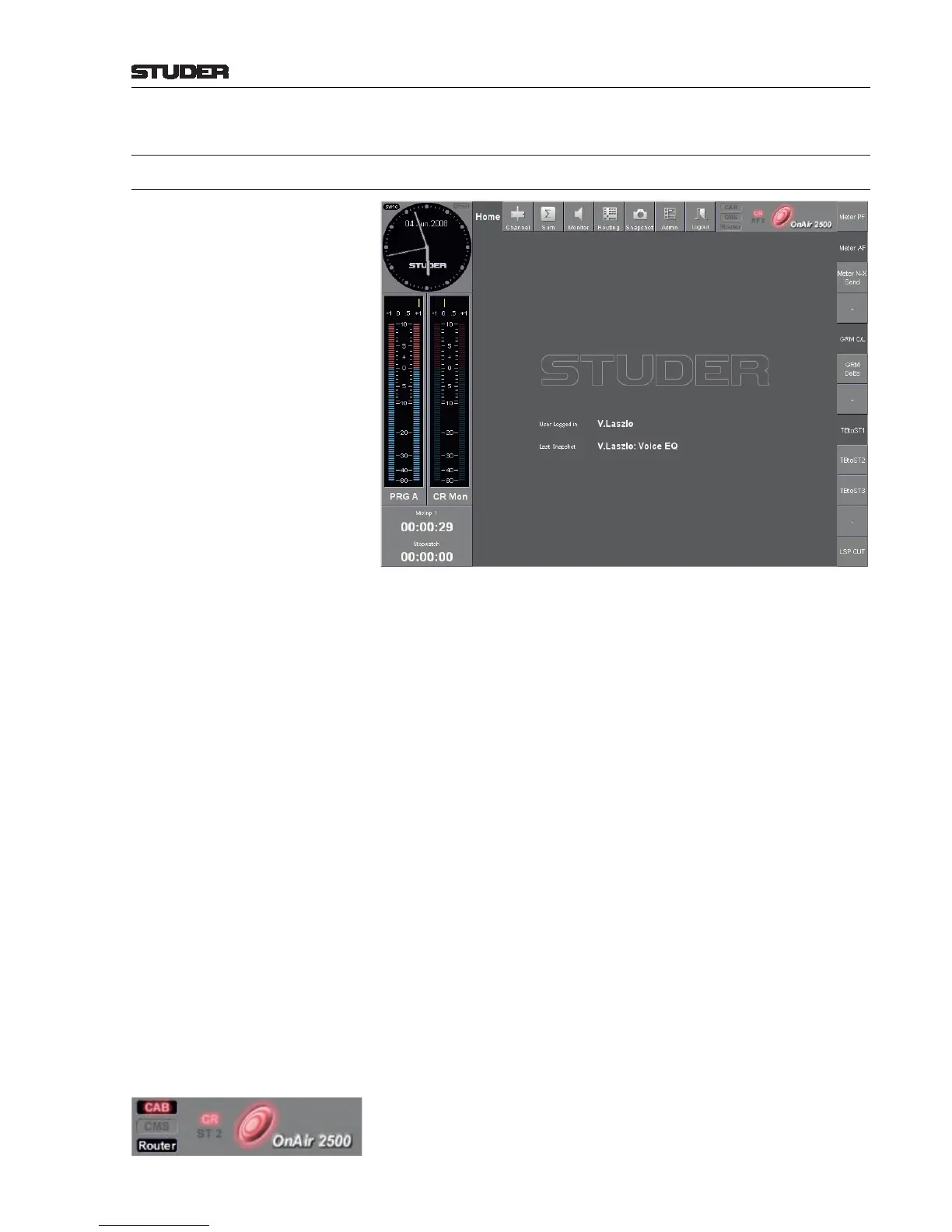
The left, upper, and right borders of the central screen are always visible. They
contain (clockwise):
• User stop watch
• Global fader stop watch
• Two stereo level meters, a phase correlation meter for each of them, and
a label below the level meters that indicates the current meter tap point
• Watch (real-time clock and date)
• Menu buttons
• Red light indicators, “Frisbee” On-Air indicator symbol
• Configurable function buttons.
The central area of the central screen displays the user currently logged in as
well as the name and owner of the last loaded snapshot.
An error message window is displayed on the home page as well in case an
internal error should occur.
Level Meter Two 130-segment stereo bar graph level meters with configurable charac-
teristics and scale. The 0 dB indication automatically considers the selected
headroom (i.e., 0 dB indication = 0 dB
FS
– selected headroom).
Above each level meter bar graph a phase correlation meter with a –1...+1
scale allows judging the mono compatibility of the audio signal (the more
positive the indication is, the better mono compatibility is given).
Level Meter Label The label below each level meter bar graph indicates the current meter tap
point. Touching this label toggles through a configurable list of the available
tap points.
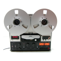
Red Light Indicators The CR and ST 2 (control room and studio) indicators work in parallel
with the red light indicators on the monitoring/talkback module. An on-air
condition is indicated by changing the color of the “Frisbee” symbol next to
the OnAir 2500 label from blue to red.