01/02
4-47
8825/8830 Printer
REP 9.2
Repairs and Adjustments
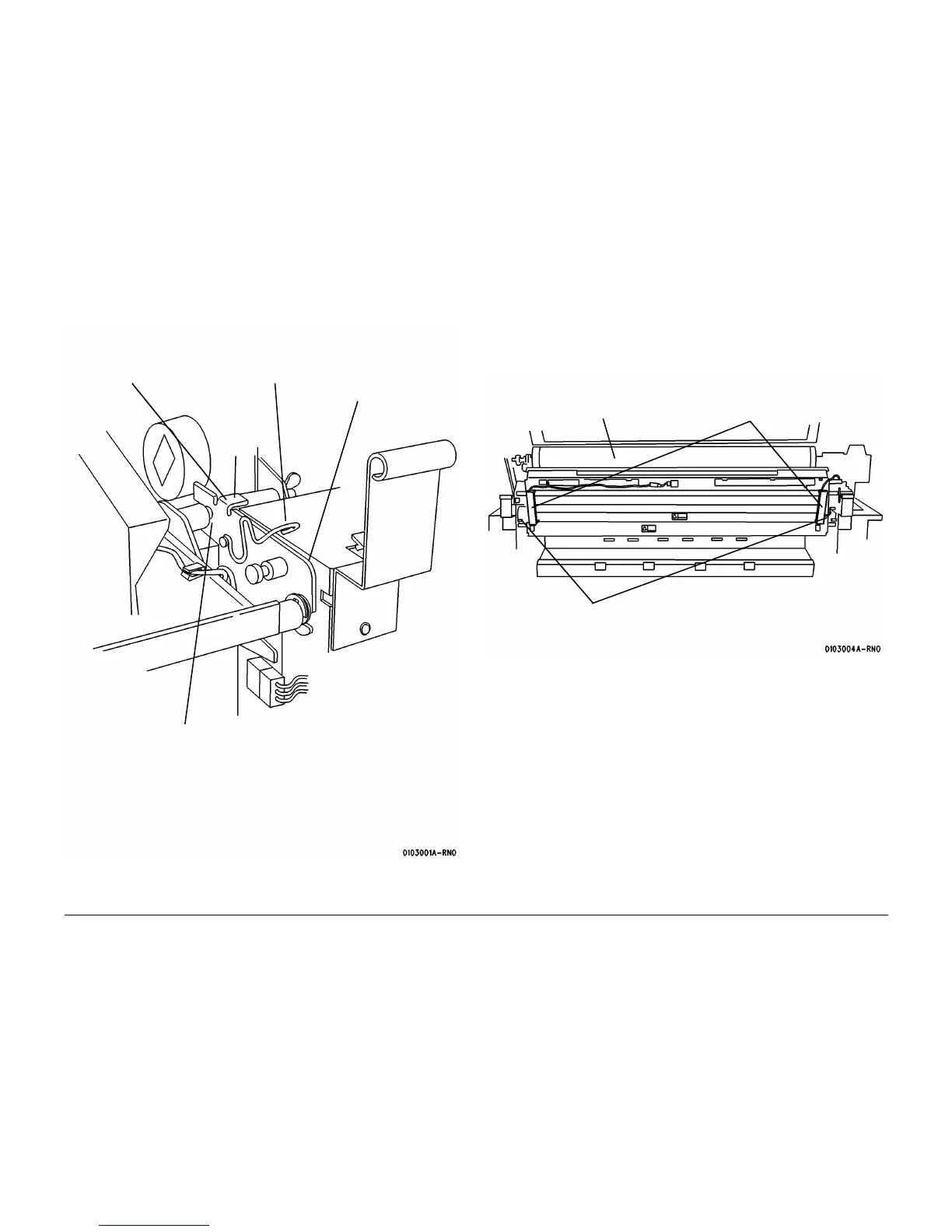
5. (Figure 1): Prepare the Front and Rear Support Brackets for raising the Xerographic Mod-
ule to the Service Position.
Figure 1 Preparing the Support Bracket
NOTE: The latches that secure the Xerographic Module to the Printer Frame are spring-loaded
and will automatically engage the holes. The latches have a 1/4 turn lockout feature that may
be used to prevent actuation during reinstallation of the Xerographic Module. When performing
the following step, ensure that the spring-loaded feature is active.
6. (Figure 2): Using the handles on the Web Oiler Assembly, rotate the Xerographic Module
90 degrees so that the latches lock into the holes in the frame.
Figure 2 Latching the Xerographic Module at the Service Position
NOTE: In the following steps, “Left” and “Right” describe machine locations as observed when
you are facing the Xerographic Module at the left side of the Printer.
1
Lift the bracket at the
tab in order to discon-
nect the spring
2
Pull the spring away
from the shaft
3
Push the bracket down
to the horizontal posi-
tion
5
Using the handles on the Web
Oiler Assembly, pull back the
Xerographic Module so that the
groove on the shaft is captured
by the Support Bracket ((Front
and Rear)
Tab
4
Perform Steps 1
through 3 for the Rear
Support Bracket
Handles
1
Rotate the Xerographic
Module 90 degrees
2
Ensure that the Xerographic Module is latched to
the frame
 Loading...


