01/02
4-86
8825/8830 Printer
REP 9.20
Repairs and Adjustments
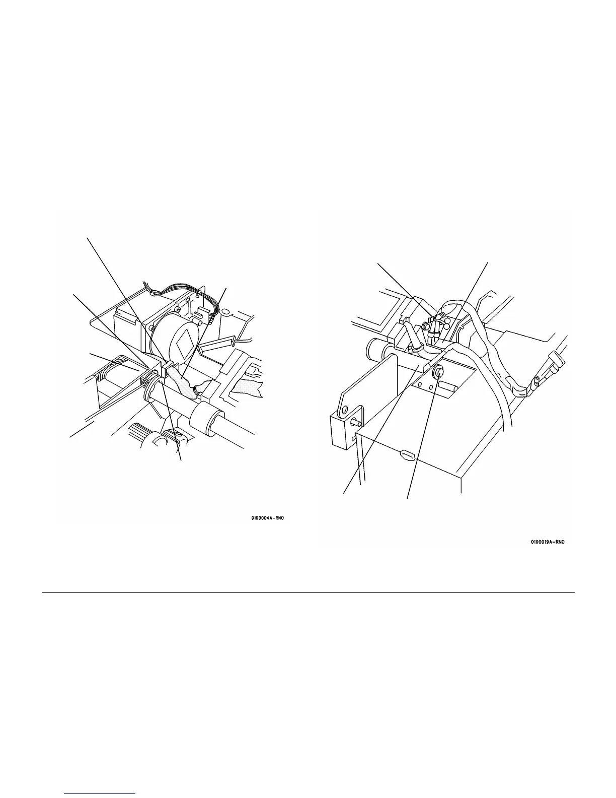
15. (Figure 9): Complete the removal preparation on the front area of the Image Module
Assembly.
Figure 9 Preparing to Remove the Image Module Assembly (View looking at the Front
from the Right Side)
16. (Figure 10): Continue to pull the Video Cable through the hole after releasing it from the
cable guides.
Figure 10 Preparing to Remove the Image Module Assembly (View looking at the Rear
from the Right Side)
17. Lift out the Image Module Assembly / Pivot Bar combination.
2
Remove the screw
and the cable clamp
Spring
1
Remove the
bolt from the
end of the
shaft
4
Remove the two
E-rings
3
Pull the harness up to
the level of the Image
Module
Top Cover
Support
Bracket
2
Unfasten the Video
Cable
1
Disconnect the con-
nectors and remove
the Charge Scorotron
Harness
4
Remove the
spacer
3
Remove the bolt

 Loading...


