01/02
6-44
8825/8830 Printer
Removal Procedure
General Procedures
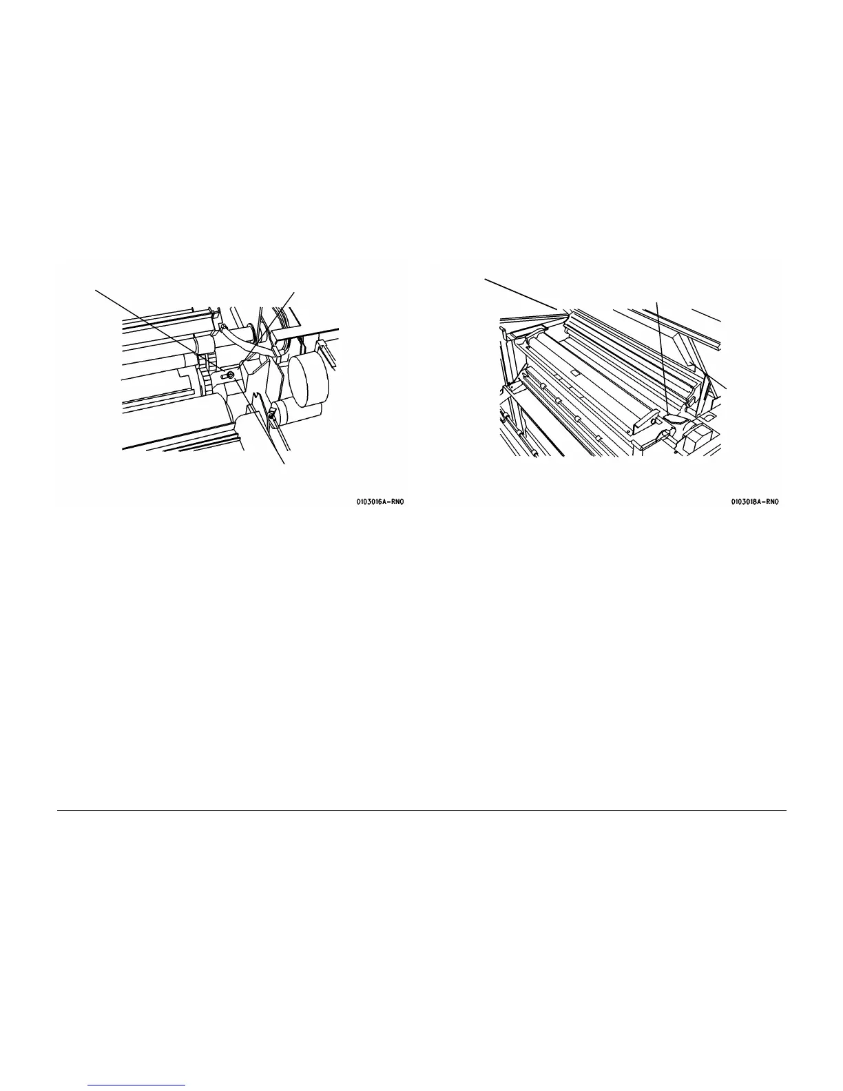
Figure 2 Engaging the Shipping Brackets
17. ( Figure 3): Install the shipping pads.
Figure 3 Installing the Shipping Pads
18. Remove the Charge Scorotron Assembly ( REP 9.8), wrap the assembly in bubble pack,
and place it in a Media Supply Drawer.
19. ( Figure 4): Open the Media Transport Cover and secure the Stripper Finger Assembly
with a cable tie.
1
Loosen screw
2
Slide bracket onto the shaft
3
Retighten screw
4
Repeat steps 1 through 3
on other side
Image Module at Service Position
1
Install the shipping pads, one on
each end of photoreceptor
2
Install the
foam pads,
one on each
side
 Loading...


