01/02
4-4
8825/8830 Printer
REP 3.1
Repairs and Adjustments
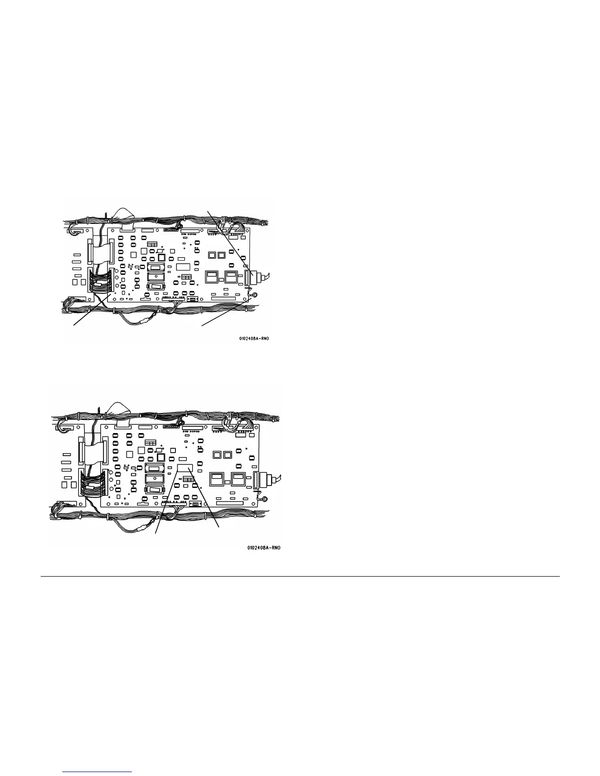
4. (Figure 2): Disconnect the 10 connectors from the Printer Main PWB.
Figure 2 Ground Connector location on Main PWB
5. Pull the 8 plastic fasteners outward and remove the Printer Main PWB.
6. (Figure 3): Remove the NVM integrated circuit from the existing Main PWB.
Figure 3 NVM Integrated Circuit
NOTE: Position the Pin 1 Locating Dot as shown.
2
Disconnect Ground Connector
1
Disconnect connectors (8)
3
Disconnect Image Bar connector
NVM Integrated Circuit
Pin 1 locating dot

 Loading...


