10
Sharing an input/output unit between multiple engines (Standard mode)
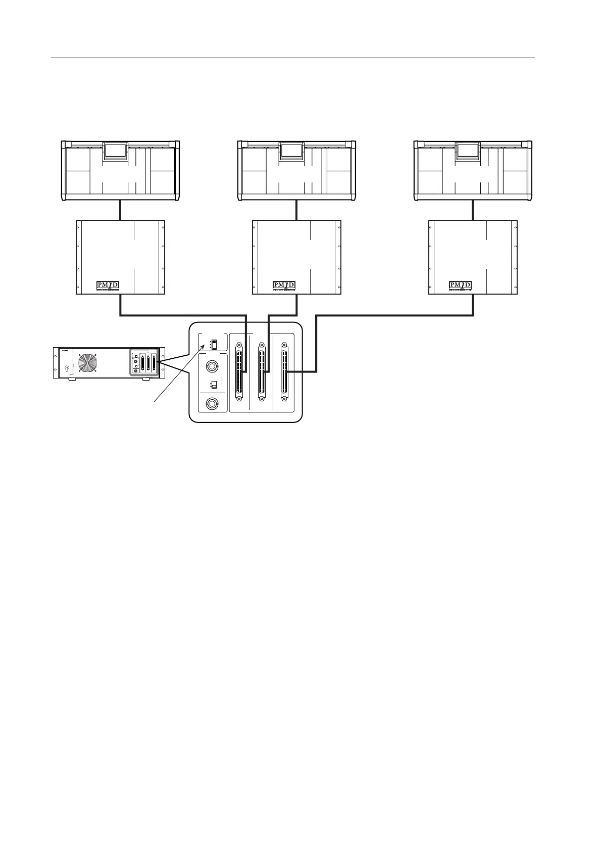
The following diagram shows example connections when sharing an AI8 input unit in Standard mode. The AI8’s OUT-
PUT jacks A–C are connected to engines (DSP1D) 1–3, each with a different Unique ID.
The control source engine (DSP1D) is selected by the CONTROL PORT switch of the AI8. In this diagram, the CON-
TROL PORT switch is set to A, so engine (DSP1D) 1 (ID=1) which is connected to the AI8’s OUTPUT jack A will be the
control source, and will adjust all parameters including gain.
Although engine (DSP1) 2 (ID=2) and engine (DSP1D)
3 (ID=3) can also recognize the AI8, they cannot adjust
its parameters. (Unit-related parameters will be shaded
in the screen.) Settings for the entire unit (such as word
clock-related settings) will also be controllable only from
engine (DSP1D) 1 (ID=1). If you want to change the
control source engine (DSP1D), change the position of
the AI8’s CONTROL PORT switch.
75Ω
IN
CB A
OUTPUT
ON
OFF
OUT
A
B
C
CONTROL
PORT
WORD
CLOCK
75Ω
IN
CB A
OUTPUT
ON
OFF
OUT
A
B
C
CONTROL
PORT
WORD
CLOCK
AI8 input unit
CS1D-3
DSP1D-3
[UNIQUE No. : 3]
CS1D-2
DSP1D-2
[UNIQUE No. : 2]
CS1D-1
DSP1D-1
[UNIQUE No. : 1]
CB A
Set to A