11
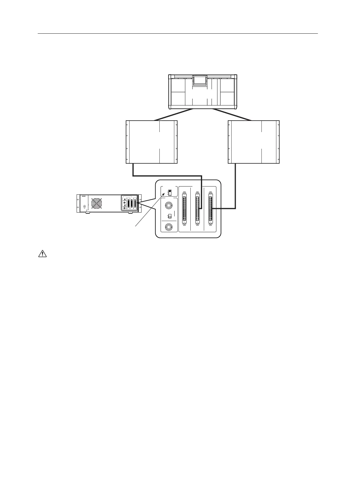
Sharing an input/output unit between multiple engines (Mirror mode)
The following diagram shows example connections when sharing an AI8 input unit in Mirror mode. The AI8’s OUTPUT
jack A is connected to engine (DSP1D-1) A, and OUTPUT jack B is connected to engine (DSP1D-2) B. In Mirror mode,
the connected jack for each unit is controlled in software. For this reason, engine A must be connected to jack A of each
unit, and engine B must be connected to jack B of each unit. (In Mirror mode, the AI8’s jack C cannot be used.)
The vacant jack of a unit used in Standard mode
must not be connected to a Mirror mode system.
Doing so will cause malfunctions.
75Ω
IN
CB A
OUTPUT
ON
OFF
OUT
A
B
C
CONTROL
PORT
WORD
CLOCK
75Ω
IN
CB A
OUTPUT
ON
OFF
OUT
A
B
C
CONTROL
PORT
WORD
CLOCK
DSP1D-B
[UNIQUE No. : 2]
CS1D-1
DSP1D-A
[UNIQUE No. : 1]
AI8 input unit
CB A
Set to A or B
INPUT
1
INPUT
1