2.13 Main Circuit Terminal Block Wiring Procedure
100 YASKAWA ELECTRIC SIEP C710617 05F YASKAWA AC Drive GA700 Technical Manual
Table 2.19 Recommended Wiring Tools
Screw Size Screw Shape Adapter
Bit Torque Driver
Model
(Tightening
Torque)
Torque Wrench
Model Manufacturer
M4 Slotted (-) Bit
SF-BIT-SL
1,0X4,0-70
PHOENIX
CONTACT
TSD-M 3NM
(1.2 - 3 N∙m)
-
M5
*1
Slotted (-) Bit
SF-BIT-SL
1,2X6,5-70
PHOENIX
CONTACT
Wire Gauge ≤
25 mm
2
(AWG 10):
TSD-M 3NM
(1.2 - 3 N∙m)
Wire Gauge ≤
25 mm
2
(AWG 10):
-
Wire Gauge ≥
30 mm
2
(AWG 8):
-
Wire Gauge ≥
30 mm
2
(AWG 8):
4.1 - 4.5 N∙m
*2 *3
M6
Hex socket cap
(WAF: 5 mm)
Bit SF-BIT-HEX 5-50
PHOENIX
CONTACT
- 5 - 9 N∙m
*2 *3
Slotted (-) Bit
SF-BIT-SL
1,2X6,5-70
PHOENIX
CONTACT
- 3 - 3.5 N∙m
*2 *3
M8
Hex socket cap
(WAF: 6 mm)
Bit SF-BIT-HEX 6-50
PHOENIX
CONTACT
- 8 - 12 N∙m
*2 *3
M10
Hex socket cap
(WAF: 8 mm)
Bit SF-BIT-HEX 8-50
PHOENIX
CONTACT
- 12 - 14 N∙m
*2 *3
*1 When wiring drive models 2056 and 4089 and smaller, select the correct tools for the wire gauge.
*2 Use 6.35 mm (0.25 in) bit socket holder.
*3 Use a torque wrench that can apply this torque measurement range.
■ Main Circuit Terminal Block Wiring Procedure
Remove the keypad and front cover before wiring the main circuit terminal block.
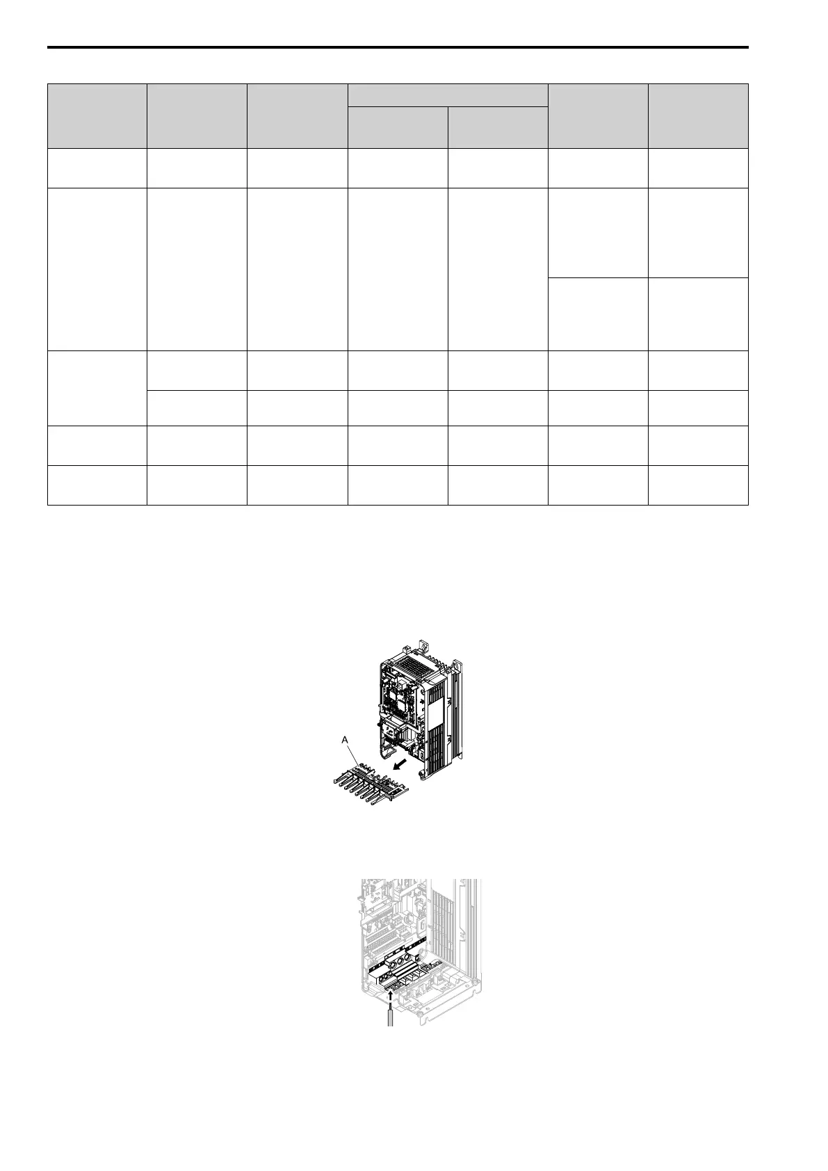
1. Pull the wiring cover forward to remove it from the drive.
A - Wiring cover
Figure 2.91 Remove the Wiring Cover
2. Put the end of a prepared wire into the terminal block.
Figure 2.92 Install the Electrical Wire