7.3 Maintenance
404 YASKAWA ELECTRIC SIEP C710617 05F YASKAWA AC Drive GA700 Technical Manual
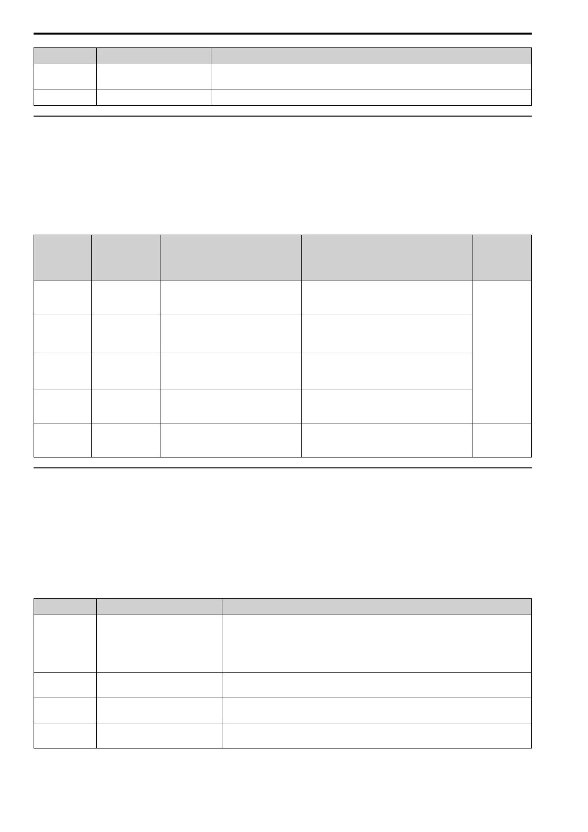
Monitor No. Component Description
U4-06 Soft charge bypass relay
Shows the number of times the drive is energized as a percentage of the performance life
of the inrush circuit.
U4-07 IGBT Shows the percentage of the maintenance period reached by the IGBTs.
◆ Alarm Outputs for Maintenance Monitors
You can use H2-xx [Multi-Function Digital Out] to send a message that tells you when a specified component is
near the end of its performance life estimate. Set the applicable value to H2-xx as shown in Table 7.9 for your
component.
When the specified component is near the end of its performance life estimate, the MFDO terminals set for H2-xx
= 2F [Maintenance Notification] will turn ON, and the keypad will show an alarm that identifies the component
to replace.
Table 7.9 Maintenance Period Alarms
Display Alarm Name Cause Solution
MFDO
(Setting
Value in H2-
xx)
LT-1
Cooling Fan
Maintenance
Time
The cooling fan is at 90% of its
performance life estimate.
Replace the cooling fan, then set o4-03 = 0
[Fan Operation Time Setting = 0 h] to reset
the cooling fan operation time.
2F
LT-2
Capacitor
Maintenance
Time
The main circuit and control circuit
capacitors are at 90% of their
performance life estimate.
Replace the board or the drive.
Contact Yaskawa or your nearest sales
representative to replace the board.
LT-3
SoftChargeBy
passRelay
MainteTime
The soft charge bypass relay is at
90% of its performance life estimate.
Replace the board or the drive.
Contact Yaskawa or your nearest sales
representative to replace the board.
LT-4
IGBT
Maintenance
Time (50%)
The IGBTs are at 50% of their
performance life estimate.
Check the load, carrier frequency, and output
frequency.
TrPC
IGBT
Maintenance
Time (90%)
The IGBTs are at 90% of their
performance life estimate.
Replace the IGBTs or the drive.
10
◆ Related Parameters
Replace the component, then set o4-03, o4-05, o4-07, and o4-09 [Maintenance Setting] = 0 to reset the
Maintenance Monitor. If these parameters are not reset after the corresponding parts have been replaced, the
Maintenance Monitor function will continue to count down the performance life from the value that was reached
with the old part. If the Maintenance Monitor is not reset, the drive will not have the correct value of the
performance life for the new component.
Note:
The drive installation environment has an effect on the maintenance period.
Table 7.10 Maintenance Setting Parameters
No. Name Function
o4-03 Fan Operation Time Setting Sets the value from which to start the cumulative drive cooling fan operation time in
10-hour units.
Note:
When o4-03 = 30 has been set, the drive will count the operation time for the
cooling fan from 300 hours and U4-03 [Cooling Fan Ope Time] will show 300 h.
o4-05
Capacitor Maintenance Setting Sets the value from which to start the count for the main circuit capacitor
maintenance period as a percentage.
o4-07 Softcharge Relay Maintenance
Set
Sets as a percentage the value from which to start the count for the soft charge bypass
relay maintenance time.
o4-09 IGBT Maintenance Setting Sets the value from which to start the count for the IGBT maintenance period as a
percentage.