Mechanical & Electrical
Installation
2
2.9 Change the Drive Enclosure Type
YASKAWA ELECTRIC SIEP C710617 05F YASKAWA AC Drive GA700 Technical Manual 57
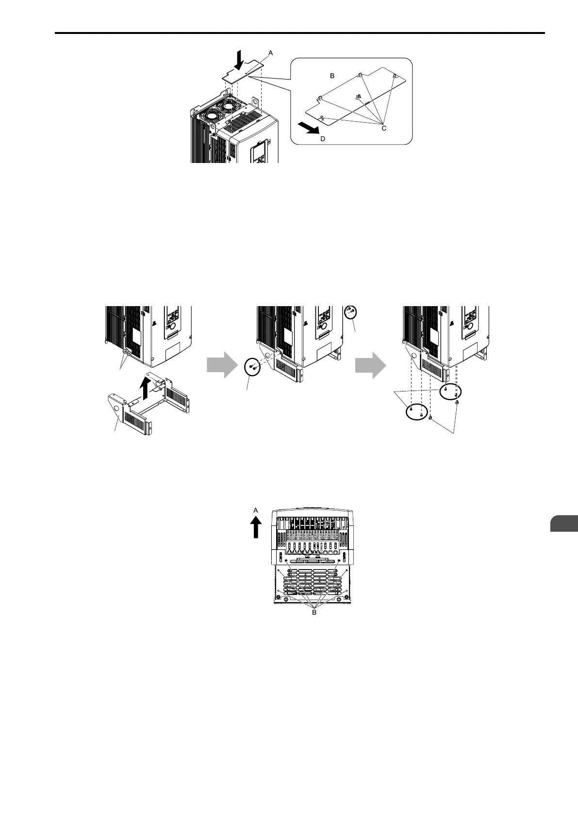
A - Mark
B - Rear side of top protective cover
C - Hooks
D - Front of drive
Figure 2.37 Attach the Top Protective Cover
■ Attach the Conduit Bracket
1. Align the screw holes on conduit bracket 1 with the screw holes on the drive and push the bracket into
position. Use the screws to attach it at the sides and the bottom.
Tighten the screws to a correct tightening torque:
• Screw A: 1.96 to 2.53 N∙m (17.35 to 22.39 lb.∙in.)
• Screw B: 0.98 to 1.33 N∙m (8.67 to 11.77 lb.∙in.)
A - Screw holes on sides
B - Conduit bracket 1
C - Screws A
D - Screws B
Figure 2.38 Attach Conduit Bracket 1
Figure 2.39 shows the locations of the screw holes on the bottom of the drive.
A - Front of drive B - Screw holes on bottom
Figure 2.39 Locations of Screw Holes on Bottom
2. Align the screw holes on conduit bracket 2 with the screw holes on conduit bracket 1.
Tighten the screws to a tightening torque of 0.98 N∙m to 1.33 N∙m (8.67 lb.∙in. to 11.77 lb.∙in.).