Mechanical & Electrical
Installation
2
2.9 Change the Drive Enclosure Type
YASKAWA ELECTRIC SIEP C710617 05F YASKAWA AC Drive GA700 Technical Manual 59
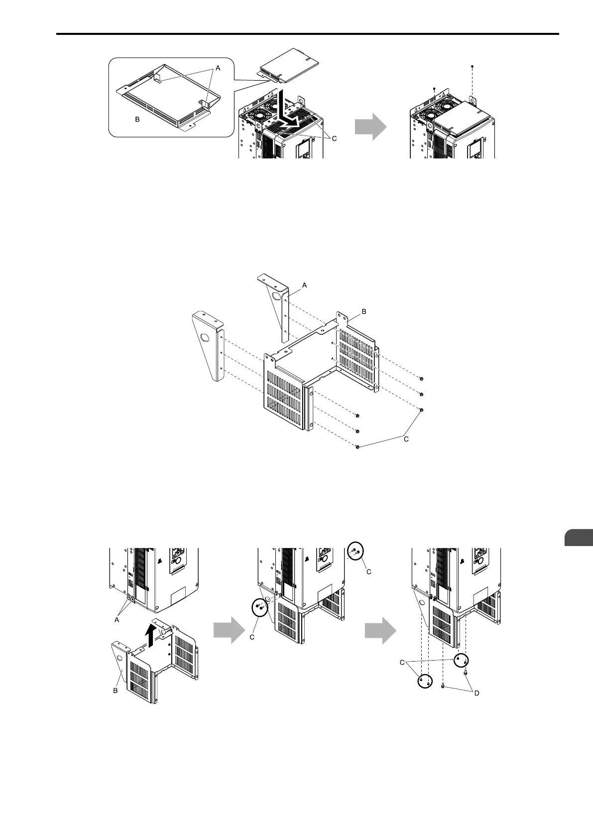
A - Hooks
B - Rear side of top protective cover
C - Temporary placement holes
Figure 2.43 Attach the Top Protective Cover
■ Attach the Conduit Bracket
1. Align the screw holes on the stay bracket with the screw holes on the base. Tighten the included screws to
a tightening torque of 0.98 N∙m to 1.33 N∙m∙(8.67 lb.∙in. to 11.77 lb.∙in.) to attach the stay bracket to the
base.
A - Stay bracket
B - Base
C - Screw
Figure 2.44 Assemble Conduit Bracket 1
2. Align the screw holes on conduit bracket 1 with the screw holes on the drive.
Tighten the included screws to a tightening torque of 3.92 N∙m to 4.90 N∙m (34.70 lb.∙in. to 43.37 lb.∙in.) to
attach the bracket to the drive.
A - Screw holes on sides
B - Conduit bracket 1
C - Screws A
D - Screws B
Figure 2.45 Attach Conduit Bracket 1
Figure 2.46 shows the locations of the screw holes on the bottom of the drive.
 Loading...


