11.3 b: Application
698 YASKAWA ELECTRIC SIEP C710617 05F YASKAWA AC Drive GA700 Technical Manual
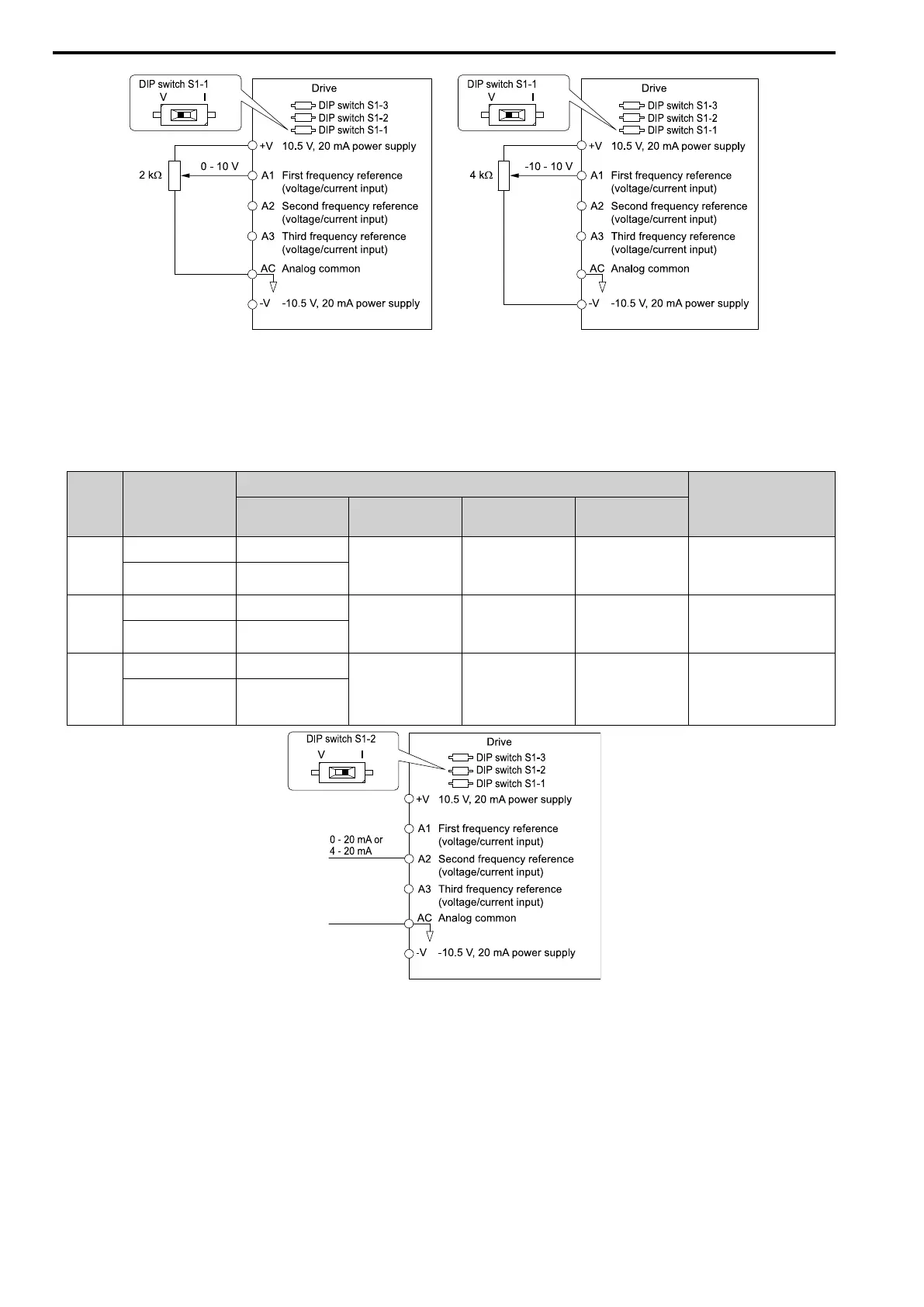
Figure 11.8 Example of Setting the Frequency Reference with a Voltage Signal to Terminal A1
Note:
You can also use this diagram to wire terminals A2 and A3.
• Current Input
Refer to Table 11.23 to use a current signal input to one of the MFAI terminals.
Table 11.23 Frequency Reference Current Input
Termi
nal
Signal Level
Parameter Settings
Note
Signal Level
Selection
Function
Selection
Gain Bias
A1 4 mA to 20 mA H3-01 = 2 H3-02 = 0
[Frequency
Reference]
H3-03 H3-04 Set DIP switch S1-1 to
“I” for current input.
0 - 20 mA H3-01 = 3
A2 4 mA to 20 mA H3-09 = 2 H3-10 = 0
[Frequency
Reference]
H3-11 H3-12 Set DIP switch S1-2 to
“I” for current input.
0 - 20 mA H3-09 = 3
A3 4 mA to 20 mA H3-05 = 2 H3-06 = 0
[Frequency
Reference]
H3-07 H3-08 Set DIP switch S1-3 to
“I” for current input.
Set DIP switch S4 to
“AI” for analog input.
0 - 20 mA H3-05 = 3
Figure 11.9 Example of Setting the Frequency Reference with a Current Signal to Terminal A2
Note:
You can also use this diagram to wire terminals A1 and A3.
Changing between master and auxiliary frequency references
Use the multi-step speed reference function to change the frequency reference input between terminals A1, A2,
and A3.
2 : Memobus/Modbus Communications
Use MEMOBUS/Modbus communications to enter the frequency reference.
3 : Option PCB
Use a communications option card or input option card connected to the drive to enter the frequency reference.
 Loading...


