EasyManuals Logo

Zebra ZM400 Series User Manual

Zebra ZM400 Series
470 pages
To Next Page IconTo Next Page
To Previous Page IconTo Previous Page
Page #197 background imageLoading...
Page #197 background image
197
Corrective Maintenance
Printhead Latch
8/9/07 ZM400/ZM600 Maintenance Manual 14207L-001 A
3. Snug the two strike plate mounting screws.
4. Using the gap pin gauge, verify that the inside print mechanism adjustment is correct. A
slight friction should be felt when sliding the inside pin in and out of the inside hole.
5. Is the adjustment acceptable?
6. Loosen the two strike plate screws.
7. See Figure 70. Install the print mechanism adjustment cam on the printer frame with the
screw provided in the kit.
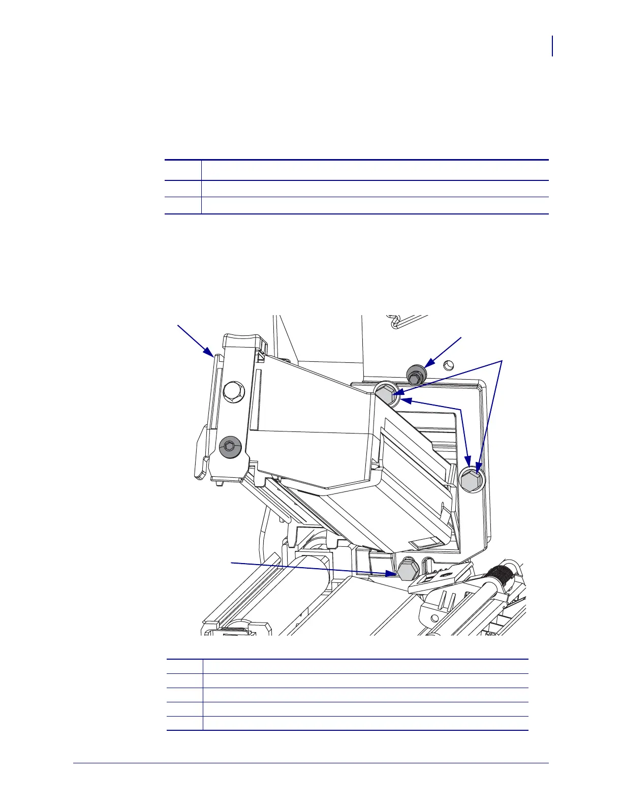
Figure 70 • Print Mechanism Mounting Screws
If… Then…
No Continue with step 6.
Yes Go to step 13.
1
Print mechanism
2
Adjusting cam
3
Hex head mounting screws (2)
4
Large washer
5
Hex head mounting screw no washer
1
2
4
3
5

Table of Contents

Questions and Answers:

Question and Answer IconNeed help?

Do you have a question about the Zebra ZM400 Series and is the answer not in the manual?

Zebra ZM400 Series Specifications

General IconGeneral
Max Print Width4.09 inches (104 mm)
Max Print Speed10 inches per second (254 mm per second)
Print MethodThermal Transfer/Direct Thermal
Resolution203 dpi (8 dots/mm)
ConnectivityUSB 2.0, Serial RS-232, Parallel, Internal Ethernet (10/100), optional wireless
Media Width1"/25.4 mm to 4.5"/114 mm
Media Length0.25 to 39 inches (6 to 991 mm)
Media Thickness0.0023"/0.058 mm to 0.010"/0.25 mm
Ribbon Width1"/25.4 mm to 4.33"/110 mm
Ribbon Length1476 feet (450 m)
Supported Media TypesContinuous, die-cut, notch, black-mark
Operating Temperature40°F to 105°F (5°C to 40°C)
Storage Temperature-40°F to 140°F (-40°C to 60°C)

Related product manuals