237
Corrective Maintenance
Ribbon/Head Open Sensor Assembly
8/9/07 ZM400/ZM600 Maintenance Manual 14207L-001 A
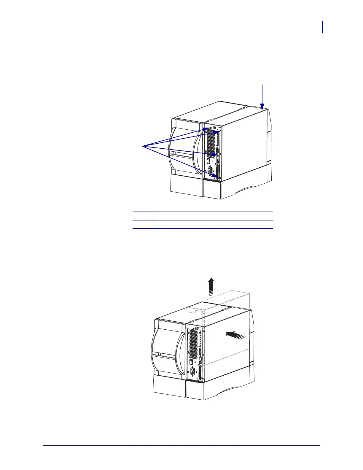
5. See Figure 103. Remove the four mounting screws on the rear of the printer.
Figure 103 • Remove the Electronics Cover Mounting Screws
6. See Figure 104. Remove the electronics cover by pressing in on the electronics cover with
the palm of your hand, and then lifting up on the cover.
Figure 104 • Remove the Electronics Cover
1
Electronics cover
2
Mounting screws (4)
2
1
 Loading...