239
Corrective Maintenance
Ribbon/Head Open Sensor Assembly
8/9/07 ZM400/ZM600 Maintenance Manual 14207L-001 A
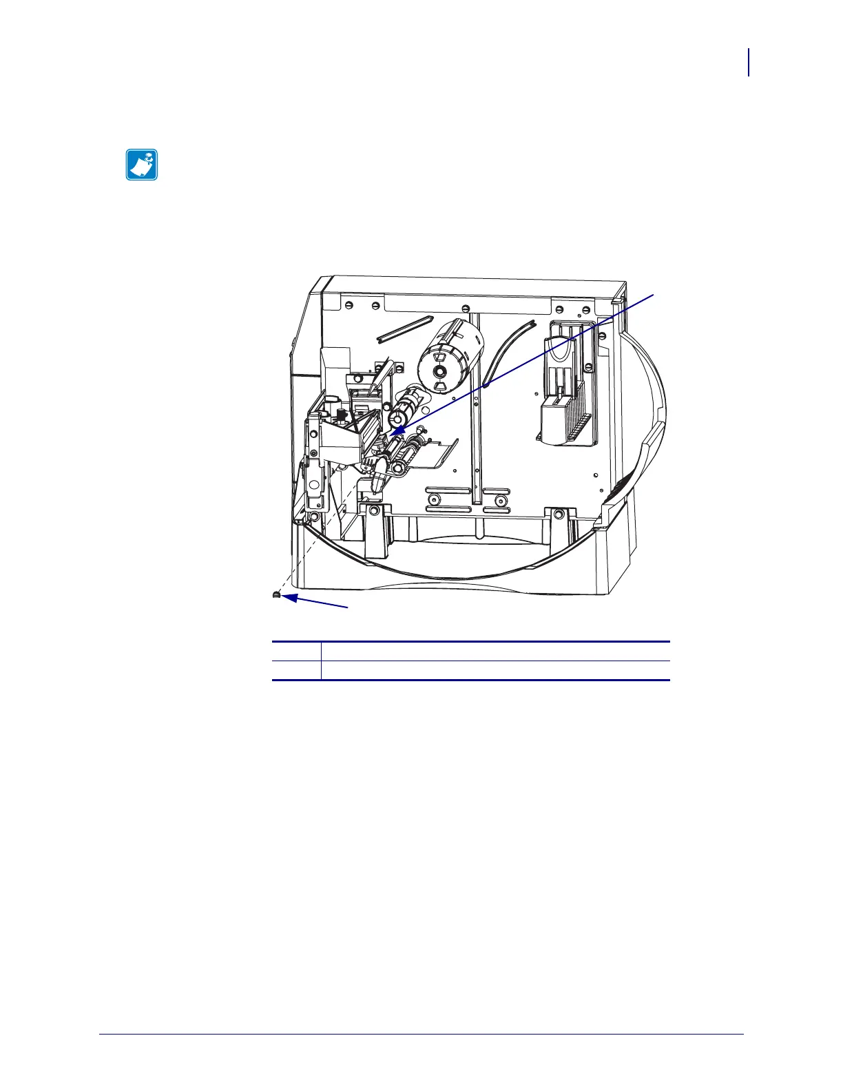
4. See Figure 106. Remove the screw securing the ribbon/head open sensor assembly.
5. Pull the ribbon sensor cable and connector through the main frame.
Figure 106 • Ribbon Sensor Removal and Installation
Note • You may find it easier to lay the printer on its side for easy access to the mounting
screw.
1
Ribbon/Head open sensor assembly
2
Mounting screw
1
2
 Loading...