Corrective Maintenance
Drive System
248
14207L-001 A ZM400/ZM600 Maintenance Manual 8/9/07
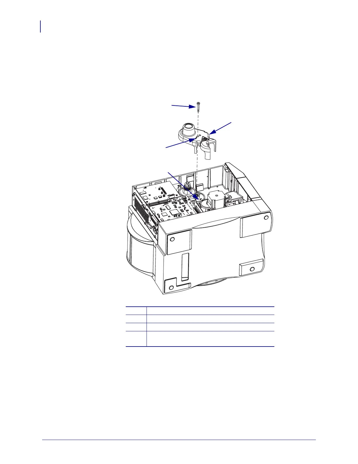
3. See Figure 114. Mark the proper mounting hole in the gear cover.
You will use this mark as areference when you reinstall the gear cover.
4. Remove and discard the gear cover mounting screw.
Figure 114 • Remove the Gear Cover
5. Slide the cover off the drive assembly and discard.
6. Mark the outside facing side of the compound gear and remove it.
You will use this mark as areference when you reinstall the compound gear.
7. Turn the printer back up on its base.
1
Mounting screw
2
Gear cover
3
Mark the proper mounting hole.
4
Compound gear. Mark the side of the compound
gear that faces out.
1
2
3
4
 Loading...