305
Corrective Maintenance
Ribbon Supply Spindle
8/9/07 ZM400/ZM600 Maintenance Manual 14207L-001 A
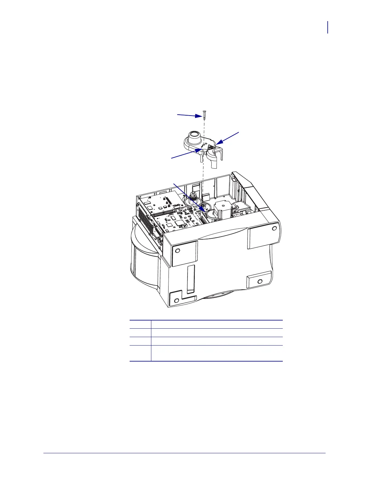
2. See Figure 168. Mark the proper mounting hole in the gear cover.
This is done to be sure it is mounted correctly when the ribbon take-up spindle installation
is complete.
3. Remove the gear cover mounting screw.
Figure 168 • Remove the Gear Cover
4. Slide the cover off the drive assembly.
5. Mark the outside facing side of the compound gear and remove it.
This is done to be sure it is mounted correctly when the ribbon take-up spindle installation
is complete.
1
Gear cover
2
Mounting screw
3
Mark the proper mounting hole.
4
Compound gear. Mark the side of the compound
gear that faces out.
1
2
3
4
 Loading...