Chapter 4 INDIVIDUAL FORMATS FOR CONTROL COMMANDS
“1” = 1bit, “2” = 2 bits, “3” = 3 bits, “4” = 4 bits,
“5” = 5 bits, “6” = 6 bits, “7” = 7 bits, “8” = 8 bits
“0” = CS, “1” = VD, “2” = HD, “3” = OSW0,
“4” = OSW1, “5” = GSW0, “6” = GSW1
“0” = CS, “1” = VD, “2” = HD, “3” = OSW0,
“4” = OSW1, “5” = GSW0, “6” = GSW1
“0” = VS, “1” = VD, “2” = HD, “3” = OSW0,
“4” = OSW1, “5” = GSW0, “6” = GSW1
“0” = HS, “1” = VD, “2” = HD, “3” = OSW0,
“4” = OSW1, “5” = GSW0, “6” = GSW1
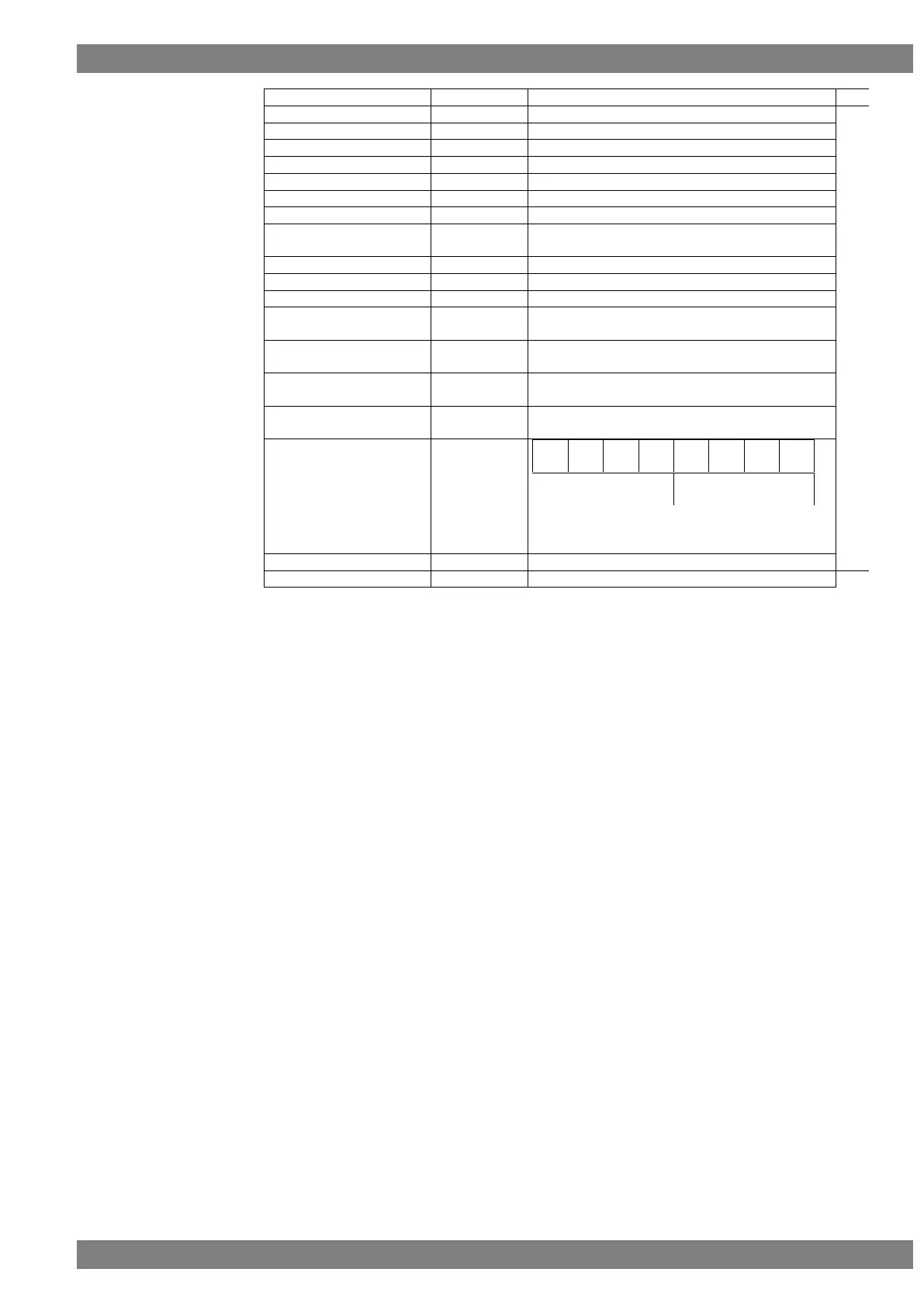
‘4xH’ is set on the basis of the above bit layout.
“x” is substituted for by the value that has raised
each of the bits.
'40H' (“@” in ASCII code)
Fig. 4-31-2
 Loading...