EasyManua.ls Logo

ASTRO VG-871 - SPAR4 [20 H 26 H]: Parallel Data Registration

ASTRO VG-871
499 pages
Print Icon
To Next Page IconTo Next Page
To Previous Page IconTo Previous Page
Loading...
32
2.7 SPAR4 [20H 26H]: Parallel data registration
Function: This command registers the parallel data of the designated program. When
the program number is 0, it writes the data into the buffer RAM. When it is
9999, it writes the data into the command work RAM.
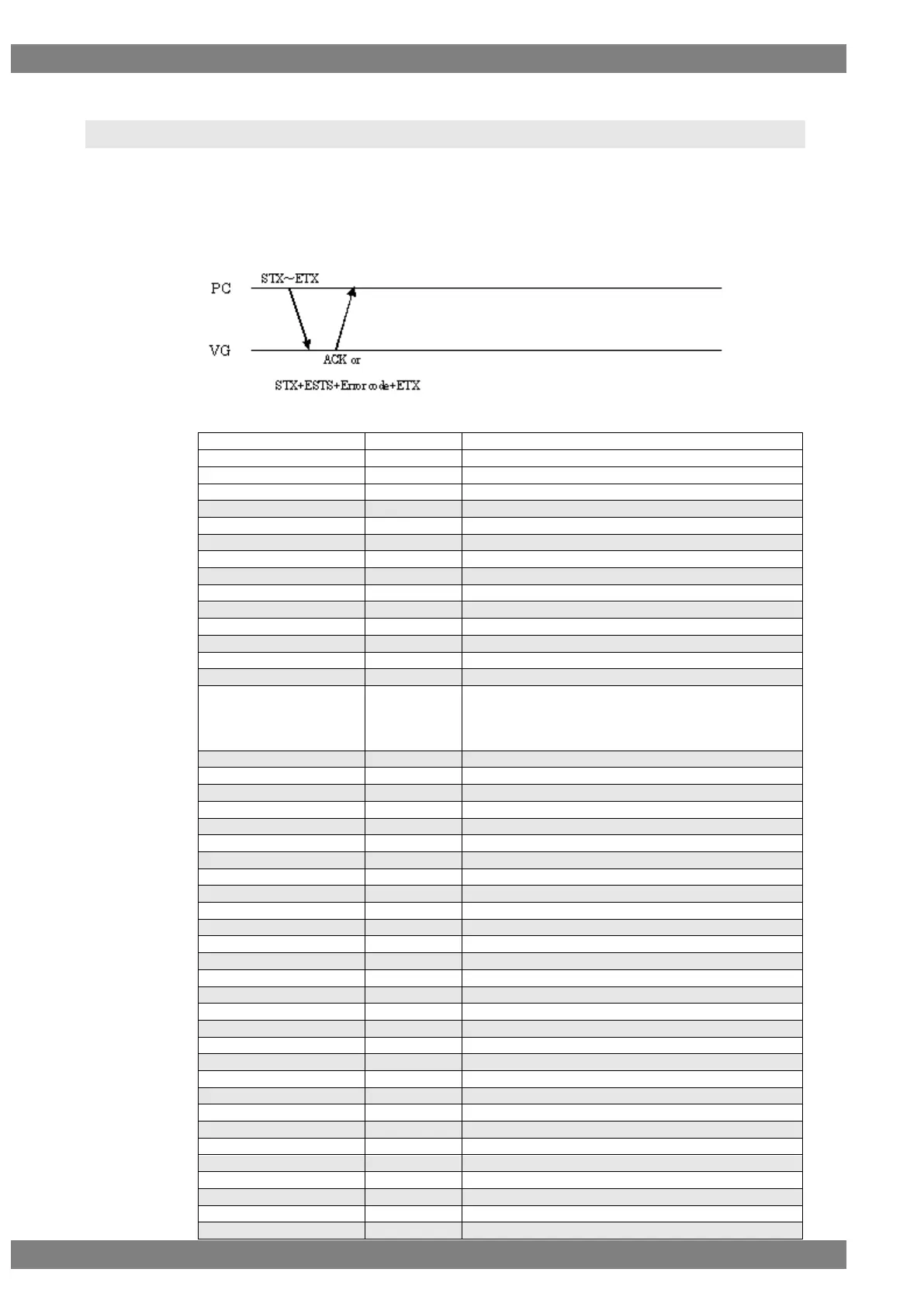
Sequence: Type 2
Command:
STX
1 byte
02H
VG4CMD
1 byte
FDH
SPAR4
2 bytes
20H 26H
Program number
1 to 4 bytes
“0” to “1000”, “9999”
,
1 byte
2CH (Delimiter)
HD Polarity
1 byte
“0” = Nega, “1” = Posi
,
1 byte
2CH (Delimiter)
VD Polarity
1 byte
“0” = Nega, “1” = Posi
,
1 byte
2CH (Delimiter)
CS Polarity
1 byte
“0” = Nega, “1” = Posi
,
1 byte
2CH (Delimiter)
Clock Polarity
1 byte
“0” = Nega, “1” = Posi
,
1 byte
2CH (Delimiter)
Disp Polarity
1 byte
“0” = Nega, “1” = Posi
,
1 byte
2CH (Delimiter)
Dual Mode
1 byte
“0” = Single (Auto)
“1” = Dual (8 bits)
“2” = Single (8 bits)
“3” = Single (16 bits)
,
1 byte
2CH (Delimiter)
Ch1 Output Enable
1 byte
“0” = Hi-Z, “1” = ON
,
1 byte
2CH (Delimiter)
Ch1 Clock
1 byte
“0” = Hi-Z, “1” = ON
,
1 byte
2CH (Delimiter)
Ch1 Sync
1 byte
“0” = Hi-Z, “1” = ON
,
1 byte
2CH (Delimiter)
Ch1 Power
1 byte
“0” = Hi-Z, “1” = ON
,
1 byte
2CH (Delimiter)
Ch1 RGB Polarity
1 byte
“0” = Nega, “1” = Posi
,
1 byte
2CH (Delimiter)
Ch1 SW1
1 byte
“0” = CS, “1” = VD, “2” = HD, “3” = Low, “4” = High
,
1 byte
2CH (Delimiter)
Ch1 SW2
1 byte
“0” = CS, “1” = VD, “2” = HD, “3” = Low, “4” = High
,
1 byte
2CH (Delimiter)
Ch1 SW3
1 byte
“0” = CS, “1” = VD, “2” = HD, “3” = Low, “4” = High
,
1 byte
2CH (Delimiter)
Ch2 Output Enable
1 byte
“0” = Hi-Z, “1” = ON
,
1 byte
2CH (Delimiter)
Ch2 Clock
1 byte
“0” = Hi-Z, “1” = ON
,
1 byte
2CH (Delimiter)
Ch2 Sync
1 byte
“0” = Hi-Z, “1” = ON
,
1 byte
2CH (Delimiter)
Ch2 Power
1 byte
“0” = Hi-Z, “1” = ON
,
1 byte
2CH (Delimiter)
Ch2 RGB Polarity
1 byte
“0” = Nega, “1” = Posi
,
1 byte
2CH (Delimiter)
Ch2 SW1
1 byte
“0” = CS, “1” = VD, “2” = HD, “3” = Low, “4” = High
,
1 byte
2CH (Delimiter)

Table of Contents

Related product manuals