Chapter 2 INDIVIDUAL FORMATS FOR VG CONTROL COMMANDS
2.10 LLVDS4 [20H 29H]: LVDS data readout
Function: This command reads the LVDS data of the designated program. When the program
number is 0, it reads out the data from the buffer RAM. When the program has any
number from 1001 to 2000, the command reads out from the fixed data. When the
program number is 9999, the command reads the data from the command work
RAM.
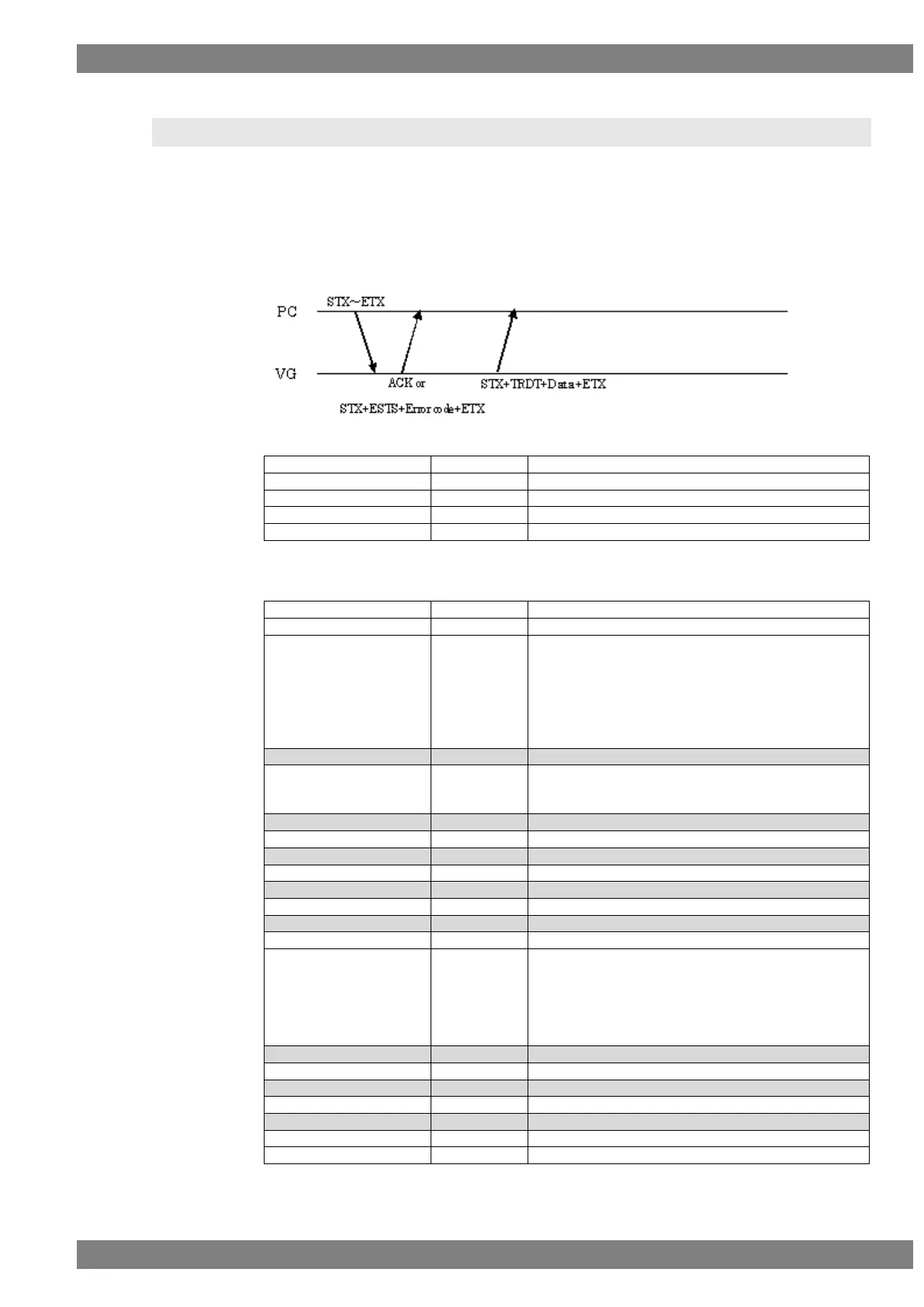
Sequence: Type 3
Command:
Fig. 2-10-1
Data:
“1” = Dual (Auto)
“2” = Quad (10 bits)
“3” = Single (10 bits)
“4” = Single (Mbits)
“5” = Dual (10 bits)
“6” = Dual (Mbits)
“1” = Split into 2 (Valid at Dual or Quad setting)
“2” = Split into 4 (Valid at Quad setting)
"1"=DEF2(OpenLDI)
"2"=USER1
"3"=USER2
"4"=USER3
"5"=refer Program
Fig. 2-10-2