Chapter 2 INDIVIDUAL FORMATS FOR VG CONTROL COMMANDS
2.14 LPT4 [20H 2DH]: Pattern data readout
Function: This command reads the pattern data of the designated program. It selects the
pattern block to be set as a parameter and receives the corresponding data. When
the program number is 0, it reads out the data from the buffer RAM. When the
program has any number from 1001 to 2000, the command reads out from the fixed
data. When the program number is 9999, the command reads the data from the
command work RAM.
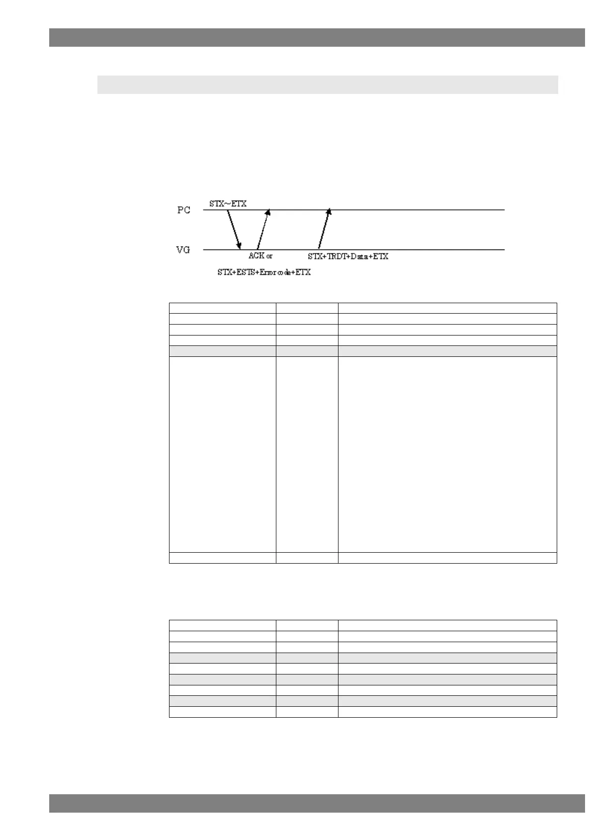
Sequence: Type 3
Command:
“2” = Character
“3” = Crosshatch
“4” = Dot
“5” = Circle
“6” = Burst
“7” = Window
“8” = Cursor
“9” = Pattern name
“10” = Color bar
“11” = Gray scale
“12” = Ramp
“13” = Sweep
“14” = Monoscope
“15” = Raster
“16” = Checker
“17” = Optional pattern
“18” = Background color
“19” = Aspect ratio
Fig. 2-14-1
Data:
(1) Graphic color data
Fig. 2-14-2