Chapter 2 INDIVIDUAL FORMATS FOR VG CONTROL COMMANDS
2.22 LDAD4 [20H 35H]: Audio data readout (Digital)
Function: This command reads the audio data of the designated program number. When the
program number is 0, it reads out the data from the buffer RAM. When the program
has any number from 1001 to 2000, the command reads out from the fixed data.
When the program number is 9999, the command reads the data from the command
work RAM.
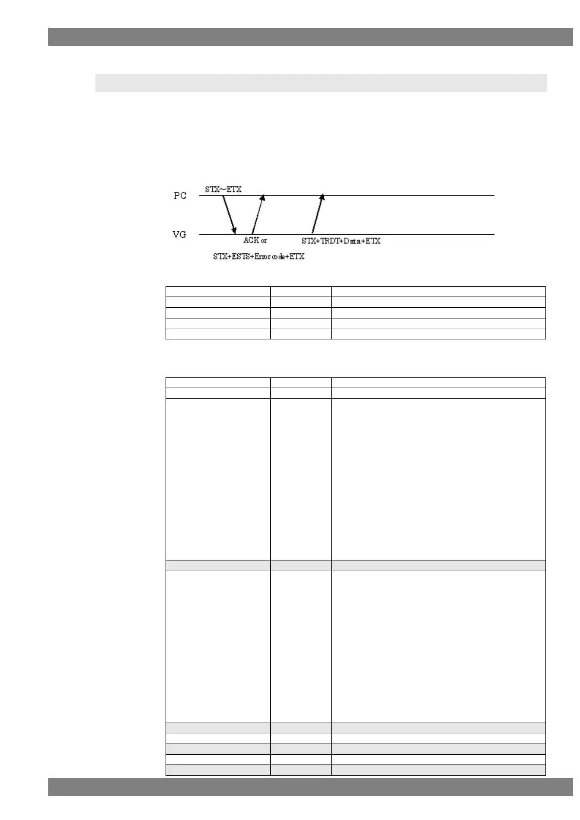
Sequence: Type 3
Command:
Fig. 2-22-1
Data:
“1” = 44.1 KHz
“2” = 32 KHz
“3” = 88.2 KHz
“4” = 96 KHz
“5” = 176.4 KHz
“6” = 192 KHz
“7” = 352.8 KHz
“8” = 384 KHz
“9” = 705.6 KHz
“10” = 768 KHz
* In case of VG-882
"0"=48KHz
"1"=44.1KHz
"2"=32KHz
“1” = Ext.OPTICAL
“2” = Ext.COAXIAL
“3” = Ext.Analog PCM
“4” = Internal PCM
“5” = Ext.Analog DSD
“6” = Internal DSD
“7” = Internal IEC
“8” = Ext.I2S Non L-PCM
"9" = Ext.I2S L-PCM
"10"=Int.L-PCM(Flash)
* In case of VG-882
"0"=OFF
"4"=Int.L-PCM
“0” = 16 bits, “1” = 20 bits, “2” = 24 bits