System Products 127
© 2020, ATEÏS. All rights reserved.
Step 1: Go to Device Management > Machine File System > RS485 Protocol Setting window,
and choose CDPM Dual Port.
Step 2: Proceed the Drag n Drop and drag the PPM AS icon from [Main-Device] and connect
it to the IDA8 processor with dual ports: the PDC 1 port or the PDC 3 port.
The PDC 2 port and the PDC 4 port cannot be functioned when connected to other remotes
such as DNM in the configuration layout, or this redundant dual port will be disable.
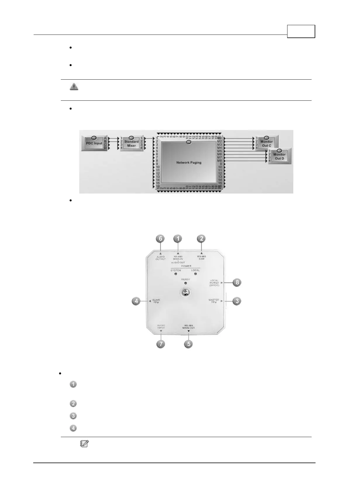
Step 3: Go to Configuration Layout, and connect the Channel A and Channel B on the PDC
Input component to the Mixer component, then connect the Mixer component to Network
Paging component. See the picture as below.
Step 4: Proceed [Compile] and [Store] action.
3.2.2 PPM JB Junction Box
3.2.2.1 Control Panel
The PPM JB is an electrical junction box which allows the chain-wiring of peripherals such as PPM-
AS, CD-8AS, CD-16AS, URC-150AS, DNM-485 etc. with IDA8/ECS/LAP G2T processor.
5 x RJ45 connectors for:
RS-485 MAIN-IN + AUDIO OUT: Connects to the PDC port of IDA8 or connects to the
previous PPM JB junction box.
RS485-SIDE: Connect to a URC device with 8-pin CAT5 cable.
MASTER PPM: Connect to a Master PPM using the supplied 10-pin CAT5 cable.
SLAVE PPM: Connect to the PPM JB for Slave PPM with 8-pin CAT5 cable.
The Slave PPM shares the same audio output with the Master PPM and can only be
 Loading...