IDA8 Global-Net User Manual128
© 2020, ATEÏS. All rights reserved.
used as a microphone.
RS-485 MAIN-OUT: Connect to next PPM JB junction box.
2 x internal screw connectors for 0 dB audio:
AUDIO OUTPUT: Audio output from PPM microphone to audio processor.
AUDIO INPUT: Audio input from audio processor to PPM's speaker for monitoring
surveillance.
1 x input for additional 24V power supply. Depending on the distance between the processor
and PPM/URC etc. devices.
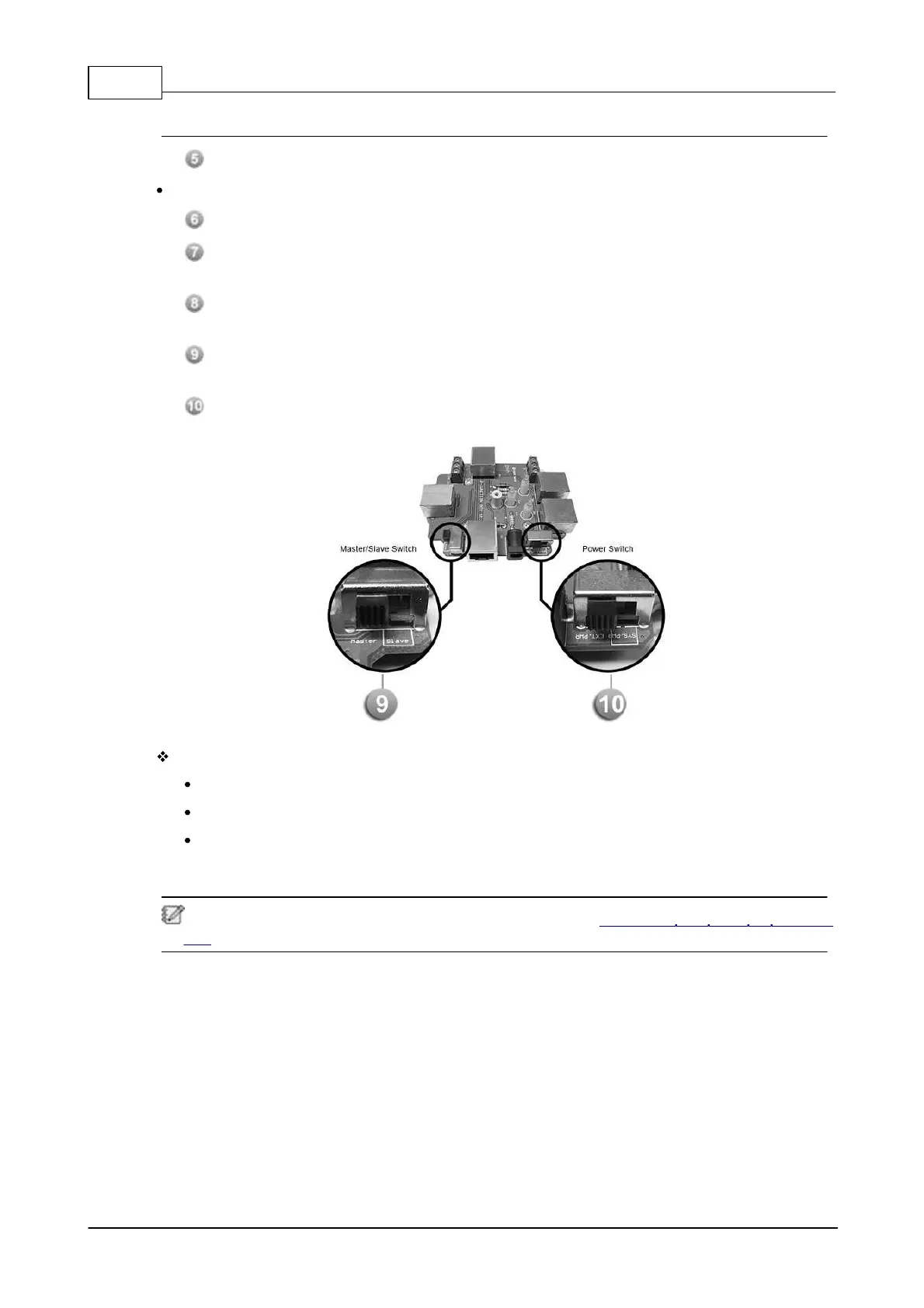
1 x internal switch inside the PPM JB junction box for PPM Master/Slave selection, see
[Picture 1] below.
1 x internal switch inside the PPM JB junction box for System or local power supply
selection, see [Picture 1] below.
LEDs:
POWER SYSTEM: Light up when the power comes from a local power supply.
POWER LOCAL: Light up when the power comes from audio processor.
READY: Light up when the PPM JB junction box is powered correctly.
3.2.2.2 Connection with PPM JB Junction Box
To know the wiring connection of PPM JB junction box, see Connection with PPM JB Junction
Box for details.
 Loading...